42 docs.carbide3d.com support@carbide3d.com 43
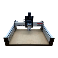
Connect the Y-Axis Cables
1. Plug the Y1- and Y2-motor cables into the
corresponding connectors on the Carbide
Motion board labeled “Y1” and “Y2.” See
Figure7‑11.
2. Plug the Y-Axis proximity switch cable into the
corresponding connector labeled “Y” on the
PCB riser board. See Figure7‑11.
Secure and Connect the X‑ and
Z‑Axis Cables
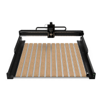
Secure the X- and Z-Axis Cables
1.
the cables at the back of the Z-Plus.
2. Gather the four X/Z-cables: the black Z-motor
lead, the X-motor lead, the Z-Axis proximity
switch cable and the X-Axis proximity switch
cable and secure them together with a cable
Figure7‑12.
3.
about 4.5 inches apart, to keep the cables
bundled together neatly in a long rope. See
Figure7‑13.
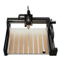
Connect the X- and Z- Cables
1. Plug the X- and Z-motor cables into the
corresponding connectors on the Carbide
Motion board labeled “X” and “Z.” See
Figure7‑14.
2. Plug the X- and Z-Axis proximity switch cables
into the corresponding connectors labeled
“X” and “Z” on the PCB riser board. See
Figure7‑14.
3.
bottom of the enclosure and re-install the
Figure7‑15.
4.
the ends of all cable ties.
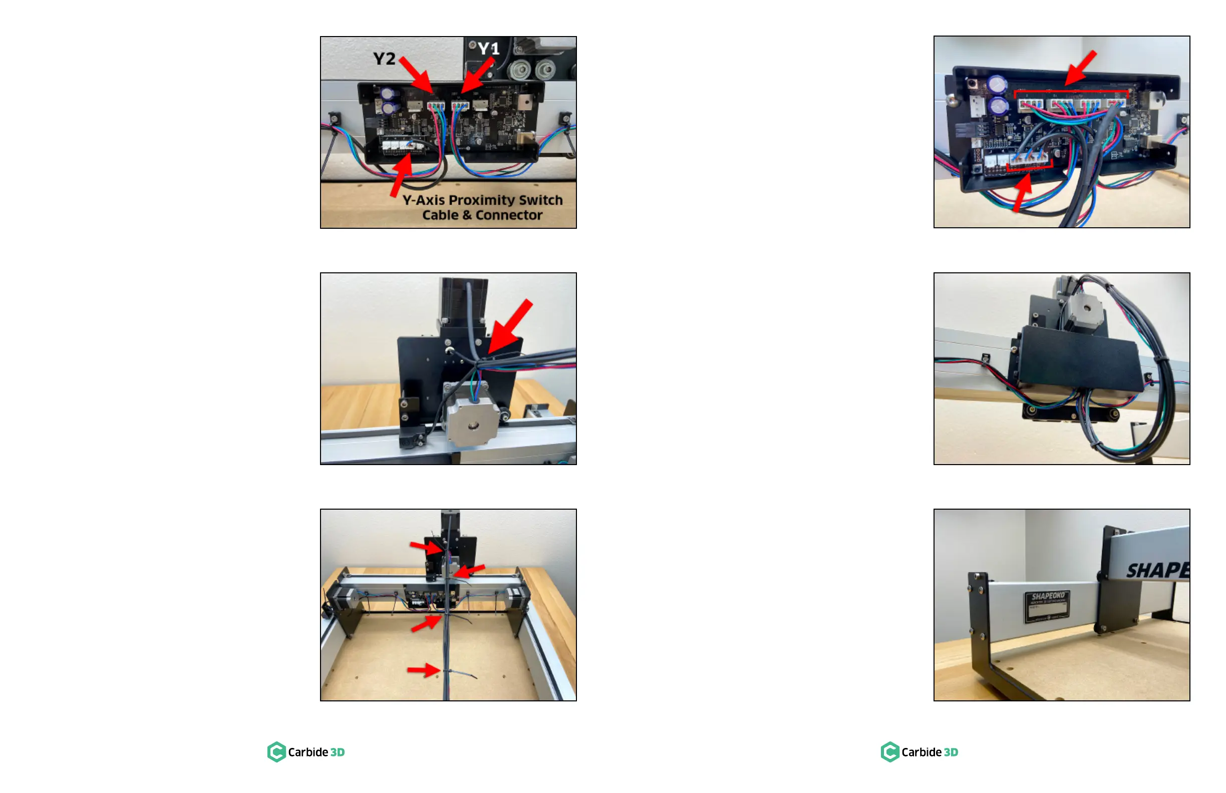
Apply the Shapeoko Build
Plate
1. Write your name on the Shapeko Build with
the included permanent marker and apply it to
the inside of the Y1-rail. See Figure7‑16.
Figure7-15
Figure7-16
Figure7-14
Figure7-12
Figure7-11
Figure7-13
 Loading...