EasyManua.ls Logo

Carbide 3D SHAPEOKO 3 - Page 5

Carbide 3D SHAPEOKO 3
31 pages
Print Icon
To Next Page IconTo Next Page
To Previous Page IconTo Previous Page
Loading...
docs.carbide3d.com support@carbide3d.com 7
Shapeoko 3 Final Assembly Box

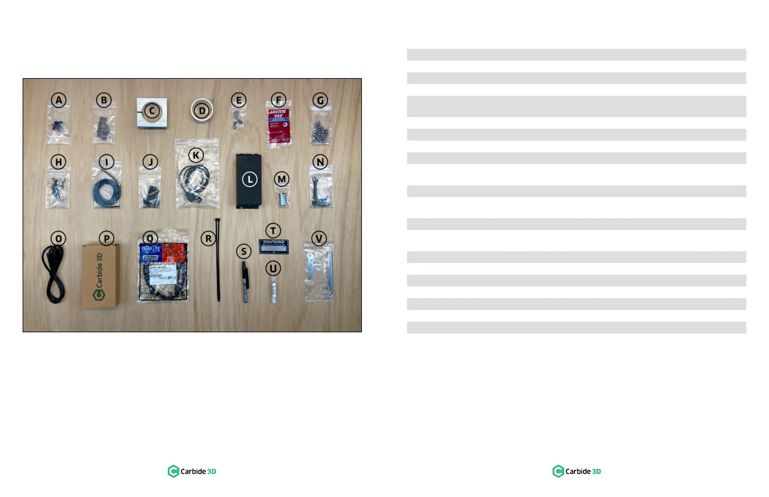
small plastic bags, and smaller bags may be packed into larger bags This box contains the items listed in the
table on the next page and shown in Figure1‑4.
Shapeoko 3 Final Assembly box contents; see Figure1‑4:
Item Description Qty
A  4
B Baseframe Hardware: M5 × 18
C Router Mount 1
D Router Mount Adapter Ring 1
E
Router Mount Hardware: M5 ××

4
F  1
G × 12mm Button Head Cap Screws 24
H × 12
I Toothed Belt 3
J
×× 8mm

12
K Proximity Switches 2
L
× 8mm

3
M PCB Riser Board 1
N
Cable Tie Mounts ×

35
O Power Cord 1
P Power Supply 1
Q USB Cable 1
R Large Zip Tie 2
S Permanent Marker 1
T Shapeoko Build Plate 1
U #201 ¼-inch Square End Mill Cutter 1
V Tool Kit: 5, 4, 3, 2.5, 2, and 1.5mm Hex Keys*; 10 and 8mm Wrenches 8

need to adjust the motor pulley set screws.
Figure1-4

Related product manuals