8200-M119-O1 Rev B 2XX-OU Installation 2
INSTALLATION, CONT.
Cable Installation
1. Loosen an unused cable gland connector for the light bar cable.
2. Insert the cable end with the two, 2-pin, connectors through the gland connector and into
the enclosure.
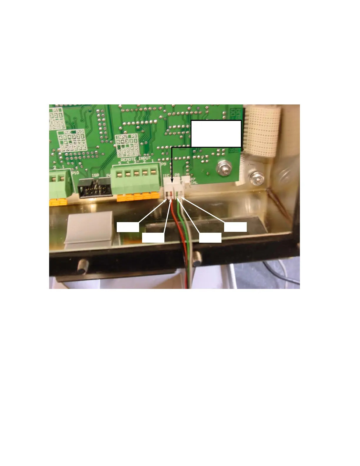
3. Plug the two connectors, side-by-side into the IIC P8 connector on the main pcb as shown
in the figure below.
Re-Installing the Rear Panel
After all terminations have been made, remove the excess cable from the instrument enclosure
and securely tighten each of the cable gland connectors. Do not over-tighten these connectors
but make certain they are snug. DO NOT USE TOOLS! Finger-tighten only! Insure any
unused gland connectors are plugged.
Make certain no cables or wires are exposed between the main housing and rear panel then
place the rear panel onto the main housing. Secure the rear panel to the enclosure with the
acorn nuts removed earlier (leave the acorn nuts off the top 3 threaded studs, refer to the
figure on the next page. Finger-tighten only!
Black
GreenRed
White
Plug in the two
connectors
here as shown.

 Loading...


