Do you have a question about the Cardinal 777 and is the answer not in the manual?
Statement regarding radio frequency interference and compliance with FCC rules.
Guidelines for instrument use, highlighting warning symbols and safety.
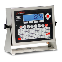
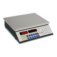
Lists key features of the 777 indicator, including keypad, display, and connectivity.
Guidelines for handling static-sensitive components to prevent damage.
Recommendations for optimal operating environment, temperature, and power.
Details on power requirements, grounding, and circuit separation for noise prevention.
Step-by-step guide for mounting the 777 indicator on a wall.
Diagram illustrating load cell pin locations and wiring connections for scale input.
Guidelines for connecting load cells with longer cables, emphasizing sense wires.
Details on connecting serial devices via COM1 (RS-232) and COM2 (RS-232/RS-485) ports.
Explanation of data formats for gross and net weight modes sent via serial port.
Describes standard keys like NET/GROSS, TARE, ZERO, UNITS, PRINT, TIME/DATE, FNCT.
How to switch between weight modes and enter/clear tare weights.
Functions for ZERO, UNITS, PRINT, TIME/DATE keys for operation and configuration.
Function of the FNCT key for returning to previous screens or menus.
Usage of ID, Alphanumeric, ENTER, BKSPC, SHIFT, NUMERIC, ALPHA keys for data entry.
General description of soft keys and their programmable functions.
How the MENU key returns the display to the Start Menu.
Details the functions of SETUP, ADJ, EXIT, STD, APP, LOAD, ESC, SEND, DSPLY keys.
Explains REVU, DIAG, APPLICATION SOFTWARE, PIB CARD TEST, RAM DISK, RAM DISK DIRECTORY.
Explains how to access and perform setup and calibration using the keypad.
Setting the interval value, decimal point, scale capacity, and weighing units.
Configuring zero tracking range and limit settings.
Setting up digital filtering levels, max filter, break range, and motion detection.
Configuring sample rate and entering calibration weights (zero load and test load).
Performing fine span adjustment and finalizing calibration, recording 'C' numbers.
Overview of transferring application programs between indicators or with a computer.
Step-by-step instructions for loading an application program into the 777.
Step-by-step instructions for sending an application program from the 777.
Guidelines for proper cleaning and care of the instrument.
Lists common error/status messages, their causes, and corrective actions.
Initial checks and possible solutions for common problems before contacting service.
Steps for installing security seals on calibration adjustments for commercial use.
General installation guidelines for the NEMA 4X enclosure model.
Connecting load cells to the 777S enclosure's terminal blocks.
Installing the RS-232 serial cable into the NEMA 4X enclosure.
Installing the RS-485 serial cable into the NEMA 4X enclosure.
Installing the KB-101 keyboard cable into the NEMA 4X enclosure.
Connecting the AC power supply to the 777S enclosure.
Installing I/O cables into the 777S enclosure and the 7781.
Labeled diagram identifying major external and internal components of the 777.
Labeled diagram showing more internal components of the 777.
List of part numbers and descriptions for components 1 through 39.
List of part numbers and descriptions for components 40 through 58.
Labeled diagram identifying components of the 777S enclosure.
Labeled diagram showing more internal components of the 777S.
Labeled diagram showing exploded view of 777S components.
List of part numbers and descriptions for 777S components 1 through 38.
List of part numbers and descriptions for 777S components 39 through 60.
Steps to enable and configure the scale totalizer feature.
How to operate the totalizer and use program commands to access its data.
Using SCLSTAT function and commands like DOZERO, DOTARE for totalizer management.