13
Fig. 3.5
ENGLISH
EVD
4
+030220227 - rel. 2.1 - 12.06.2008
READ
Parameter name Description
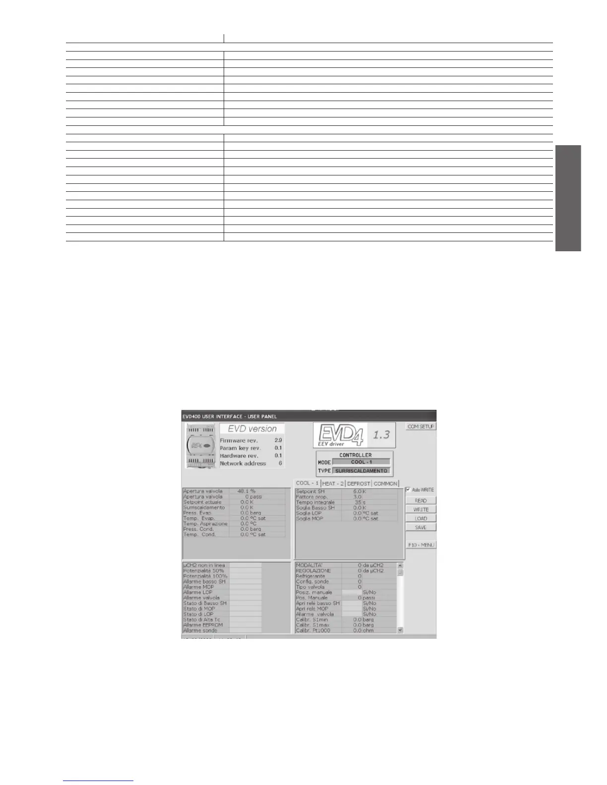
System measurements (Fig. 3.5)
EEV opening valve opening as a %
EEV position position of the valve in steps
Act. SH set current superheat set point
Superheat superheat value measured
Ev. probe press. evaporation pressure value measured
Ev. probe sat. temp. saturated gas temperature value calculated in the evaporator
Suction temp. compressor suction temperature value measured
Cond. probe press. condensing pressure value measured, from µC
2
Cond. probe sat. temp. saturated gas temperature in the condenser
Digital variables (Fig. 9)
µC
2
off line active when µC
2
is not connected to EVD
4
50% capacity active when the capacity of the circuit is 50%
100% capacity active when the capacity of the circuit is 100%
alarm Low Superheat active in low superheat conditions
alarm MOP timeout active in conditions with excessive evaporation pressure
alarm LOP timeout active in conditions with excessive evaporation pressure
EEV not closed active due to failed valve closing
Low SH status active when in low superheat control status
MOP status active when in maximum evaporation pressure control status
LOP status active when in minimum evaporation pressure control status
High Tc status active when in high condensing temperature control status
alarm Eeprom error active following an EEPROM memory error
alarm probe error active following an error on the signal from the probe
3.1.3 EVD4_UI user interface
The EVD4_UI user interface is based on the CAREL supervisor protocol and is designed for the easy and
intuitive reading or confi guration of the control parameters. The program can be started in different
confi gurations so as to display the set of parameters that is suitable for the type of installation the EVD
4
is used
in; to do this, make the connection using the name of the required confi guration. The interface confi guration
for µC
2
is shown in Fig. 3.5 and is activated by making the “EVD4_UI MCH2” connection.
as described in APPENDIX I “INSTALLING AND USING THE EVD4_UI PROGRAM”.
3.1.4 Start-up
After having connected the EVD
4
, as described in 3.1.1, connect the service serial port to a PC using the
special converter and confi gure the values of the parameters and the address using the software described
in 3.1.3 according to the application and/or systems used.
The parameters can be accessed for read and write even if the EVD4 is not powered, as the converter or
the programming key provide the power supply to the driver, excluding the valve.