19
ENG
“heaterSteam” +0300075EN - rel. 1.2 - 29.09.2015
The power line to the humidi er must be tted with a fused disconnect
protecting against short-circuits, to be mounted by the installer. The
table in chapter 12 shows the recommended cross-sections of the power
cable and the recommended sizes of the fuses; note, however, that this
data is purely indicative and, in the event of non-conformity with local
standards, the latter must prevail.
Note: in order to avoid unwanted interference, it is recommended
to keep the power cables separated from the signal ones from the
probes:
Caution: connect the yellow-green cable to the ground terminal
(GND).
4.3 Control board
The control board (S) is located inside the electrical panel, in the partition
wall.
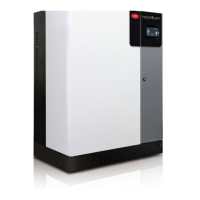
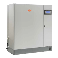
UR002-UR013 UR020-UR080
S
S
Fig. 4.i Fig. 4.j
The auxiliary connections (probes, remote terminal, alarm), must be
made by introducing the external cables into the electrical panel. For this
purpose use the smaller fairlead on the base of the machine, passing the
cables through the raceway on the internal partition to the removable
screw terminals placed on the control board.
CONTROL BOARD
1I 2I 3I 4I 5I 6I
7I
8I
1K 2K 3K
1H 2H 3H
1E 2E 3E 4E 5E 6E
7E
8E
1J 2J 3J 4J
Main board
1G 2G
G H K I J
Key:
Terminal E: reserved;
Terminal G: reserved;
Terminal H: alarm contact
Terminal K: reserved
Terminals I: control signals
Terminals J: connection
with remote terminal or supervisory system
Fig. 4.k
terminal function electrical characteristics
1I humidity level probe signal input Input impedance:
50 k if set up for 0…20 mA or 4…10 mA
60 k if set up for 0…1 V or 0…10 V or 2…10 V
2I GND
3I ≈ 32 Vdc derived from rectifying of 24 Vac; max 250mA
4I 12 Vdc stabilised accuracy ± 5%; Imax=50 mA
5I
room probe signal input
or signal from external regulator
Input impedance:
50 k if set up for 0…20 mA or 4…10 mA
60 k if set up for 0…1 V or 0…10 V or 2…10 V
6I GND
7I
remote enabling Rmax=50 Ω; Vmax=24 Vdc; Imax=10 mAdc
8I
1H NO alarm contact
250 V; 8A with resistive load; 2A with indicative load2H common alarm contact
3H NC alarm contact
1G
Reserved
2G
1J ≈ 32 Vdc derived from rectifying of 24 Vac; max 250 mA
2J L +
standard RS485
3J L -
4J GND
1K
Reserved2K
3K
Tab. 4.a

 Loading...
