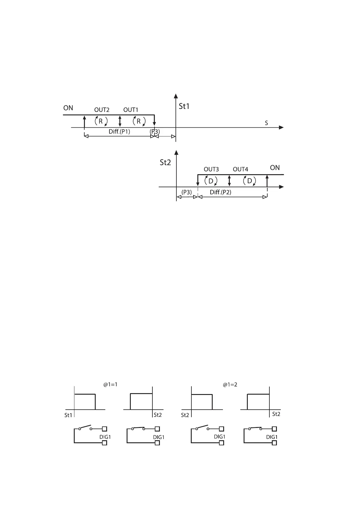
2- Nei Modi 3, 4 e 5, ponendo C33=1 la regolazione si sdoppia
come rappresentato in figura 34.
Questo perché al fine di ottenere differenziale distinti per le usci-
te Direct e Reverse, i modi 3, 4 e 5 fissano in origine la dipendenza
(DIPENDENZA) a St1 per le uscite Reverse e a St2 per le uscite
Direct utilizzando così i due differenziali P1 e P2. St2 non é visibile e
viene imposto sempre uguale a St1.
Questo non è più vero con C33=1: St2 é visibile e svincolato
richiedendo di essere impostato dall’utente.
3- Il Modo 6 dispone le uscite legate a St1 con logica Direct
(INSERZIONE positivi e DIFFERENZIALE/LOGICA negativi) con
contatto digitale aperto. La chiusura del contatto all’ingresso digitale
forza le uscite a dipendere da St2 e P2 e la logica diventa Reverse
grazie all’inversione di segno dei parametri INSERZIONE e
DIFFERENZIALE/LOGICA
(un’eventuale verifica del valore dei parametri non dipende dallo
stato dell’ingresso digitale: essi cambiano solo a livello di algorit-
mo). Posto C33=1:
- possono essere programmate uscite Direct e Reverse
tramite INSERZIONE e DIFFERENZIALE/LOGICA. La
logica costruita é valida a contatto aperto, si invertono le sin-
gole logiche con la chiusura del contatto, con
l’avvertenza che segue:
- se si seleziona DIPENDENZA=2 l’uscita relativa sarà
sempre legata a St2/P2; in pratica non cambia la
dipendenza al commutare dell’ingresso digitale.
Continuerà invece a cambiare la logica da Direct a
Reverse, ovvero vengono sempre invertiti i segni dei
parametri INSERZIONE e DIFFERENZIALE/LOGICA.
La figura sottostante rappresenta un esempio di quanto
sopra descritto. Le uscite di allarme (DIPENDENZA=3,
4...14), non dipenderanno dall’ingresso digitale.
2 - In Modes 3, 4 and 5, if C33=1, the control action modifies as
shown in the graph below (fig. 34):
Modes 3, 4, 5 determine Dependence=St1 for Reverse outputs
and DEPENDENCE=St2 for Direct outputs so as to get different
differentials. St1 always corresponds to St2 except when C33=1.
In this case St2 can be displayed and has to be set by the User.
3 - In Mode 6, when the digital contact is open, the outputs
will depend on St1 and will operate in the DIRECT logic
(ENERGIZATION positive and DIFFERENTIAL/LOGIC negative).
Closing the contact causes the outputs to depend on St2 and
P2; the operating logic will be Reverse because the sign of
ENERGIZATION and DIFFERENTIAL/LOGIC has changed.
When C33=1:
- you can program Direct and Reverse outputs by
ENERGIZATION and DIFFERENTIAL/LOGIC when the
contact is OPEN. The logic changes when the contact
closes. In this case note that:
- if DEPENDENCE=2 the relative output will always be
linked to St2/P2 (the dependence does not change
when the digital input status changes).
The operating logic, however, will continue to change,
from direct to reverse as the signs of ENERGIZATION
and DIFFERENTIAL are continually being inverted.
In the graph below the alarm outputs
(Dependence=3,4,...,14) do not depend on the digital input:
48
Fig.34
Fig.35

 Loading...


