Versione IRDRZ, con alimentazione 12/24 Vac, ingresso NTC,
Pt100, Tc J/K, V/I
Versione IRDRA: alimentazione 12/24 Vac-dc, ingresso NTC,
Pt100, Tc J/K, V, I
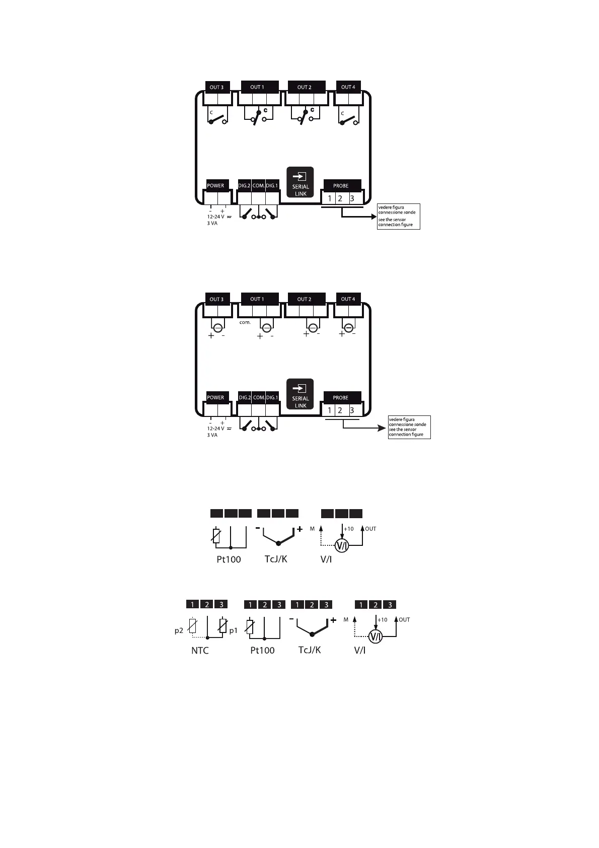
14.4 Connessione sonde
IR32 (*)
IRDR (*)
(*) ad ogni tipo di sonda corrisponde uno specifico modello
Note:
1) nel caso di sonde Pt100 a 2 fili cortocircuitare i morsetti 8
e 9 (IR32) o 2 e 3 (IRDR);
2) collegare l’eventuale schermatura della sonda alla terra del
quadro elettrico. Nel caso di termocoppie, è necessario usare
sonde con cavo compensato schermato per avere una
corretta immunità ai disturbi;
3) per le sonde in tensione o corrente considerare che la massima
tensione fornita è 10 Vdc @ 30 mA (max 8Vdc per IRDRW).
IRDRZ: power supply 12/24Vac, NTC/Pt100/J-K Tc/V/I input
IRDRA: power supply 12/24Vac-dc, NTC/Pt100/J-K Tc/V/I input
14.4 Sensor connection diagrams
IR32 (*)
IRDR
(*)
(*) each sensor corresponds to a specific model
Important:
1) When using 2-wire Pt100 sensors, short circuit
terminals 8 and 9 (IR32) or 2 and 3 (IRDR).
2) Connect the sensor shielding to the earth of the
electrical panel. When using thermocouples, use
sensors with shielded cables to avoid noises.
3) When using voltage or current sensors consider that
the maximum voltage output is 10 Vdc @ 30mA (max
8Vdc for IRDRW).
74
7 8 9
7 8 9
7 8 9

 Loading...


