EasyManuals Logo
Home>Carel>Controller>IR Series

Carel IR Series User Manual

Carel IR Series
83 pages
To Next Page IconTo Next Page
To Previous Page IconTo Previous Page
Page #71 background imageLoading...
Page #71 background image
I diagrammi sottostanti rappresentano due tipici esempi del col-
legamento della sezione alimentatore e alimentatore/ convertitore
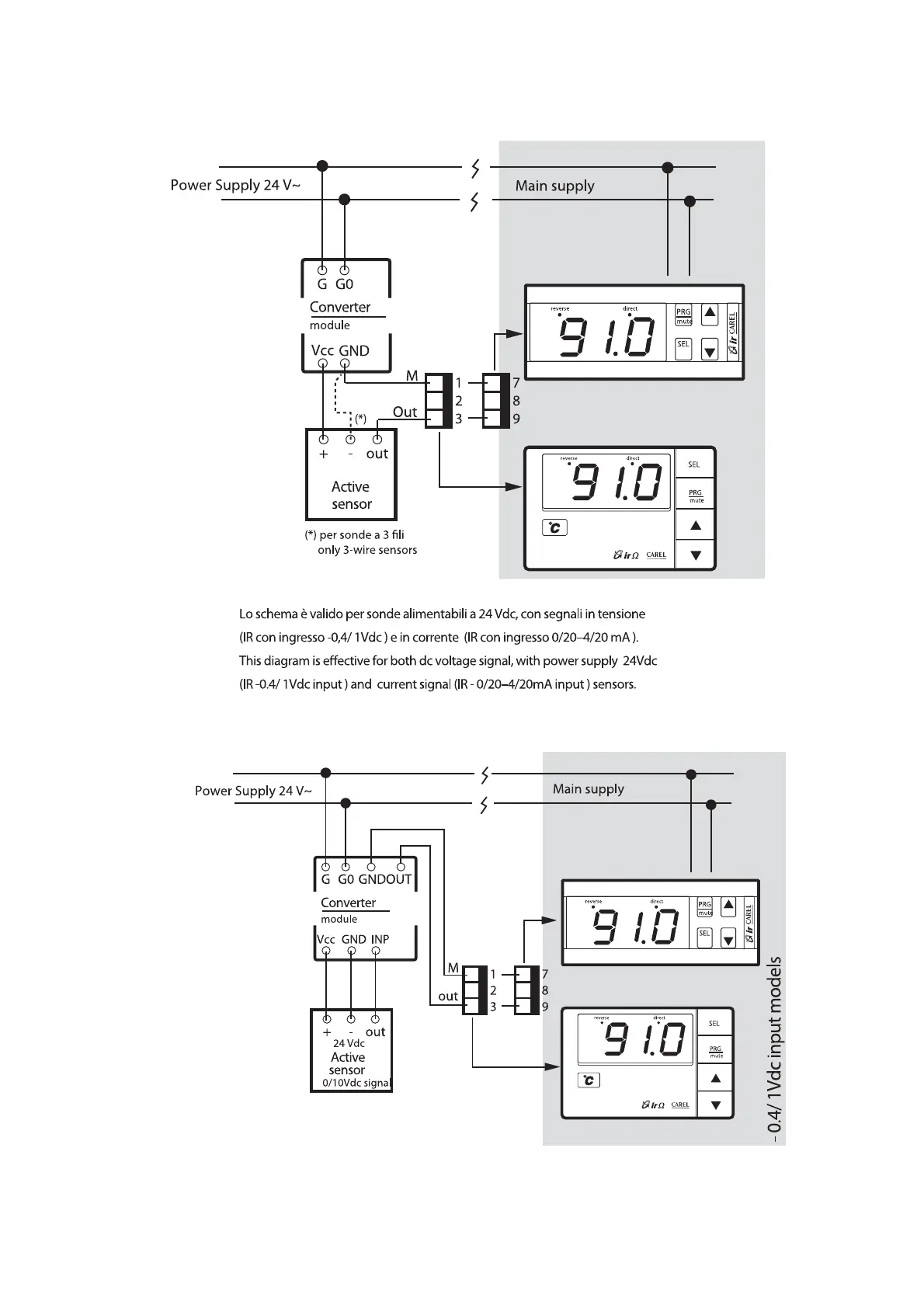
con una sonda esterna.
The figures below show two typical connections between power
supply and power supply/converter to an external sensor.
67
Fig.53
Lo schema è valido per sonde 0/10 Vdc, 3 li alimentabili a 24 Vdc
This diagram is eective for probes 0/10 Vdc, 3 wires, with power supply 24 Vdc
Fig.54

Table of Contents

Questions and Answers:

Question and Answer IconNeed help?

Do you have a question about the Carel IR Series and is the answer not in the manual?

Carel IR Series Specifications

General IconGeneral
BrandCarel
ModelIR Series
CategoryController
LanguageEnglish

Related product manuals