Cod. +030220151 - Rel. 2.1 - 04/09/98
55
TECHNICAL FEATURES
Set-point: -50T90 (-50/+90°C; -58/+194°F)
Power supply 230 ±15%
Consumption 4 VA
Precision
±1°C, ±2°F
Case plastic,
Installation incorporated
Working temperature 0÷50°C; 32÷122°F
Storage conditions -10/+70°C; 14/158 °F
Connections digital inputs and sensor on plug-in connectors, outputs on faston
connectors
Display 2 and a half digits
Signalling:
luminous
acoustic
compressor, continuous cycle, defrosting, fan, IR activated, alarm/ light
alarm buzzer
Inputs refrigerating room sensor, defrosting sensor, multi-function inputs
Type of sensor:
NTC CAREL 10KΩ a 25ºC (for codes see Carel price-list)
Relay outputs (all) Disconnection of type 1B according to ECC EN 60730-1
Compressor SPST relay, max.switching capacity: 20A/250V
Defrosting SPDT relay, max.switching capacity: 8A/250V
Fan SPST relay, max.switch.capac.: 16A/250V
Light/aux output SPST relay, max.switch.capac.: 16A/250V
Alarm output SPDT relay, max.switching capacity: 8A/250V
Kind of environmental pollution normal
Frontal protection index IP54
Important warning: the cables to be connected to the controller contacts should resist to the maximum
operating temperature which is determined by considering the expected maximum ambient temperature +
the controller overheating equal to 20°C. Moreover, it is necessary to protect the controller with a 1A,
250V protection fuse should be placed.
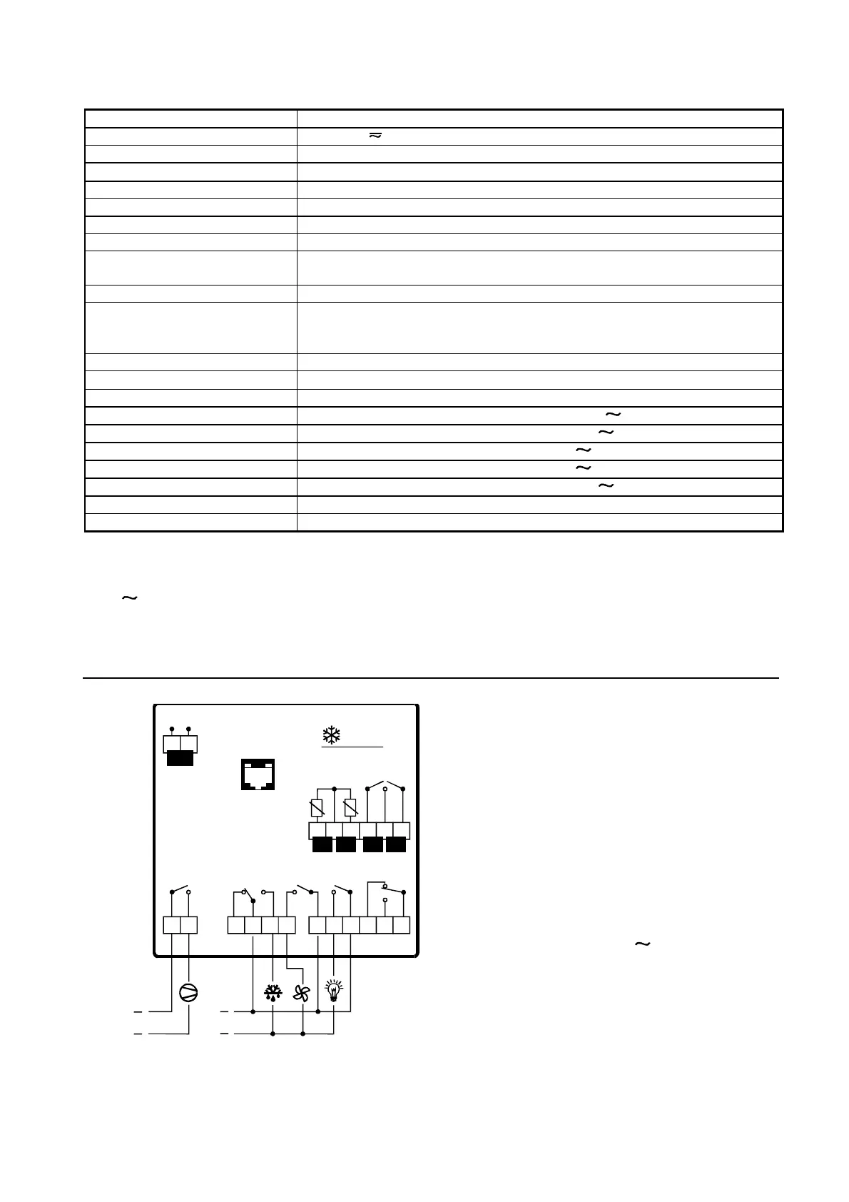
CONNECTIONS
Caution: with respect to safety rules follow the
below quoted instructions carefully:
• The cables to be connected to the controller
contacts should resist the maximum operating
temperature which is determined by considering
the maximum ambient temperature expected +
the controller auto-heating equal to 20 °C.
• Moreover, it is necessary to protect the
controller with a 1A, 250V fuse.
• Connect the terminals 12, 15 and 17 to the
same electric potential, as shown in the picture
9 10 13 1411 12 19 2017 1815 16
7 85 63 4
AMB. DEF
Dig.In1 Dig.In2
1 2
POWER
230 V~
c
c
c c
c
SERIAL LINK
Power Supply
Power Supply
ir96
 Loading...