27
ENG
ir33plus +0300028EN rel. 1.1 - 05.05.2017
Key
St Set point rd Di erential
CMP Compressor FAN Fan
Sv Virtual probe r4 Automatic night-time set point variation
Note: if one of the auxiliary outputs is used to manage the light,
lowering the curtain automatically switches the light o , while raising it
switches the light on.
8 = Low pressure switch input for pump down
See par. 6.4. Setting “A4”=8 manages the low pressure switch. The low
pressure alarm “LP” is signalled when the low pressure switch is activated:
• during normal control (c7=0) with the compressor on, or alternatively
• with pump-down function con gured (c7 >0), if the pump down valve
is open and the compressor is on.
The low pressure alarm signal is delayed by the time set for parameter
“A7”. The low pressure alarm “LP” stops the compressor.
ir33+
ON
OFF
ON
OFF
t
CMP
LOW
Pressure
switch
Pump down
valve
HIGH
OFF
ON
LP
Alarm
A7
Fig. 5.e
Key
CMP Compressor Pump down valve Pump down valve
Pressure Switch Pressure
switch
LP alarm Low pressure alarm
t Time A7 Alarm signal delay
Note: this parameter, together with c7, c8, c9 and H1, H5, allows
management of the “pump-down” algorithm (see par 6.3).
9 = Door switch with fan o only
Same as for option “A4”=5, with the di erence being that when opening
the door only the evaporator fan is switched o .
10 = Direct/reverse operation
Important: when A4 = 10, the status of digital input has priority
over the setting of parameter r3 (direct/reverse operating mode).
When the contact is open, the controller operates in “direct” mode
(cooling), when the contact is closed, in “reverse” mode (heating). A switch
can therefore be connected to select heating or cooling operation.
St
Sv
rd
OFF
ON
DI OPEN
CMP/FAN
r3 = 0, 1, 2
DIRECT
Sv
rd
OFF
ON
DI CLOSED
CMP/FAN
r3 = 0, 1, 2
REVERSE
St
Fig. 5.f
Key
St Set point Sv Virtual probe
rd Di erential CMP Compressor
FAN Fa n
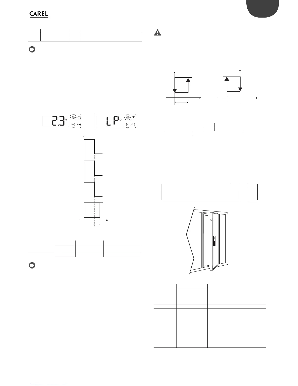
11 = Light sensor
The digital input is used to read a light sensor (P/N PSOPZLHT00, actually an
analogue input, from which a digital signal is taken using the parameter or
threshold of the light sensor).
The light sensor can be located:
• in the door jamb (ref. A);
• inside the cold room or cabinet (ref. B).
Par. Description Def Min Max UOM
AF Light sensor OFF time
0 Sensor in the door jamb
> 0 Sensor inside the cold room or cabinet
0 0 250 s
Tab. 5.h
B
A
Fig. 5.g
A (AF=0) B (AF = 1)
Light sensor
signal
The sensor signals
the opening and
closing of the door
The sensor signals the opening of the
door and detects light inside the cabi-
net/cold room. The sensor also signals
closing of the door
Inside light: on With the door open If the sensor detects light
Inside light: o With the door
closed, minimum o
time of 5 s, to avoid
rapid, successive
impulses of the light
relay
Closing of the door is measured by
time, as the inside light will illuminate
the sensor. After the time AF (>0) the
inside light is switched o for 5 secon-
ds. If the light sensor signals darkness,
the door must be closed and the light
will therefore remain o ;
if it signals light: the door is open and
the light will be switched on again.
Tab. 5.i

 Loading...


