3
drilling template
dima di foratura
29.2
138.4
165
3
Fig. 2.e
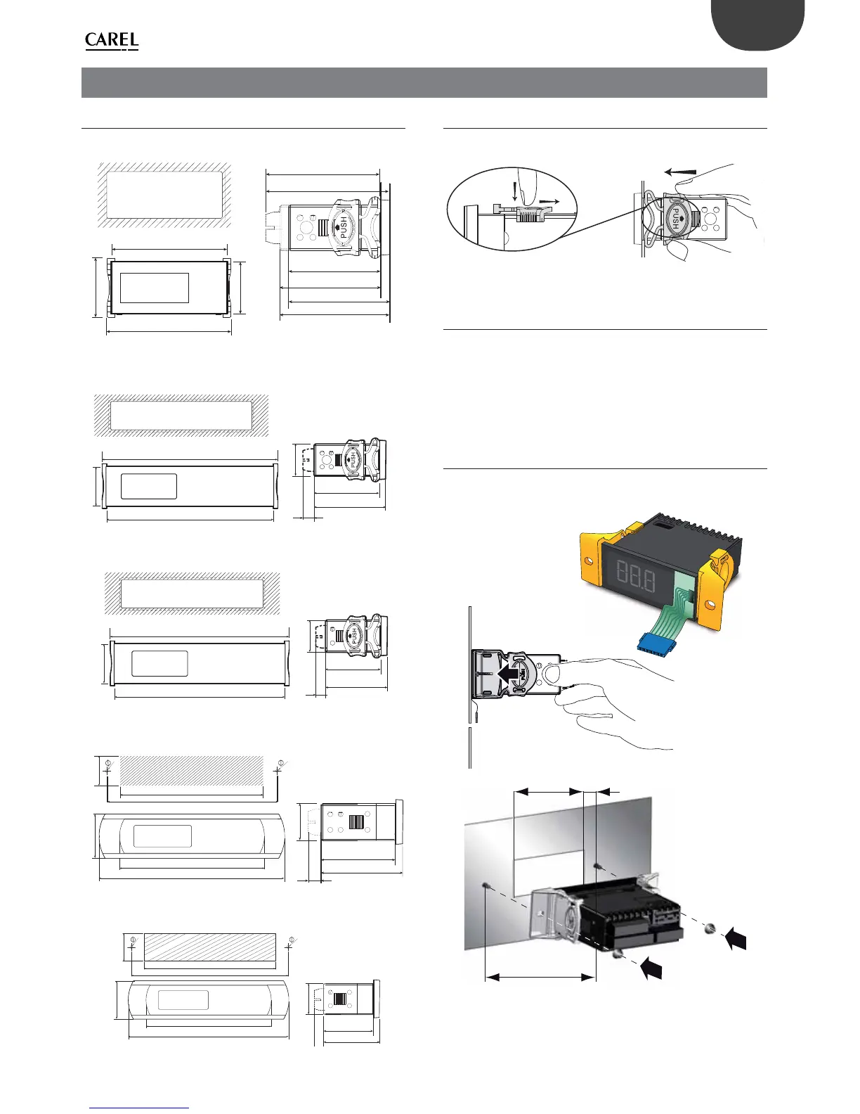
2.2 Panel mounting
To install the ir33+, ir33+ wide and ir33+ small wide controllers, use the 2
brackets shown in the gure.
Fig. 2.f
2.3 Rear panel mounting
The models with separate membrane keypad (e.g. keypad part numbers
62C716A084 and 62C716A085) should be rear panel mounted, with
the membrane keypad tted from the front; electrical connection
is performed using the ribbon cable, sliding it through the opening
provided. ir33+ and +ir33+ wide models require side brackets, inserting
the fastening screws; easy wide and easy small wide models have holes
on the side, accessible after having removed the frame.
ir33+
STEP 1
Drill the holes (ø 3 mm) with the spacing shown in the gure and make
the opening for inserting the ribbon cable.
53 mm 14,5 mm
98 mm
Fig. 2.g

 Loading...


