29
ENG
ir33plus +0300028EN rel. 1.1 - 05.05.2017
6. CONTROL
6.1 Switching the controller On/O
The controller can be switched ON/OFF from a number of sources;
keypad, supervisor and digital input. In this operating mode, the display
will be show the temperature selected for parameter /tI, alternating with
“OFF”. The digital input can be used to switch the controller on/o , setting
parameter A4/A5 to “6”. Switching on/o from digital input has priority
over the same function from the supervisor and the keypad.
Source Priority Note
Digital input 1 Disable On/O from keypad and supervisor
Keypad 2
Supervisor 3
Tab. 6.a
6.2 Virtual probe
The control output is the compressor output, which in most cases is also
associated with the evaporator fan output. The control probe is probe S1,
while probes S2, S3, S4 can be assigned functions such as product probe
(display only), defrost probe, condenser probe or frost protection probe.
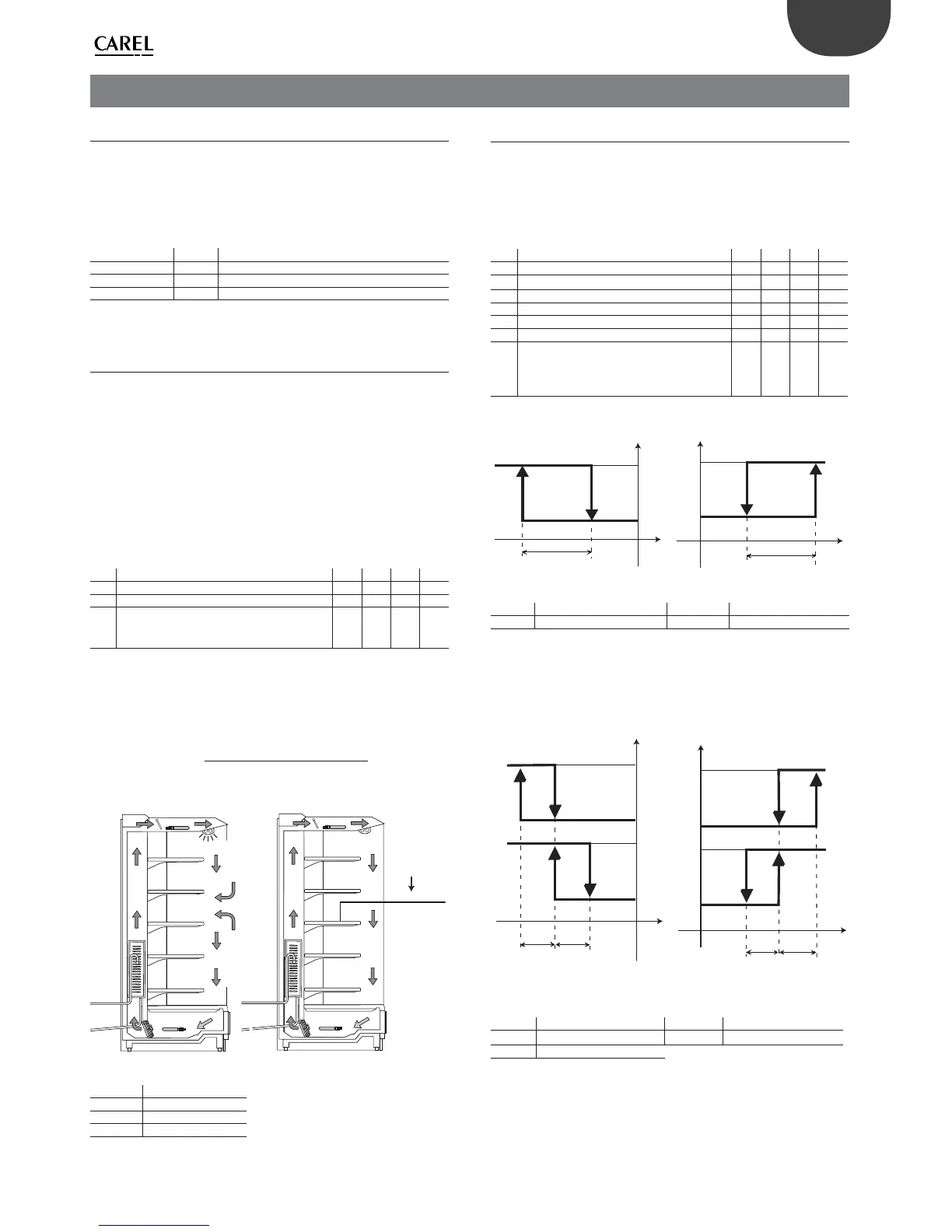
For vertical display cases, the virtual probe (Sv) should be de ned as the
control probe; this represents the half-way point between the display
case outlet and intake probes, and the reading is thus a ected by the
environmental conditions. During the day, the display case light is on and
the curtain is open to allow customers to take out the products store, at
night the curtain is closed and the light is o . Due to the lower heat load
at night, the night-time set point is increased by the value of parameter
r4.
Par. Description Def Min Max UOM
St Set point 0 r1 r2 °C/°F
r4 Automatic night-time set point variation 3.0 -20 20 °C/°F
/4 Virtual probe composition
0 = control probe S1
100 = probe S2
0 0 100 -
Tab. 6.b
Parameter /4 is used to determine the virtual probe (Sv) as the weighted
average of control probe S1 and probe S2, according to the following
formula:
Sv =
[ S1*(100 - /4) + S2*/4
100
DAY: set point = -13°C
S1
S2
NIGHT: set point = -10°C
S1
S2
Sv=(S1+S2)/
/4=50
Fig. 6.a
Key
S1 Outlet probe
Sv Virtual probe
S2 Intake probe
6.3 Set point
The reference output is the compressor output (CMP).
The controller can operate in 3 di erent modes, as selected by parameter
r3:
• direct with defrost control;
• direct;
• reverse.
Par. Description Def Min Max UOM
St Set point 0 r1 r2 °C/°F
rd Di erential 2.0 0.1 20 °C/°F
rn Neutral zone 4.0 0.0 60 °C/°F
rr Reverse di erential 2.0 0.1 20 °C/°F
r1 Minimum set point -50 -50 r2 °C/°F
r2 Maximum set point 60 r1 200 °C/°F
r3 Operating mode
0 = Direct with defrost control (cooling)
1 = Direct (cooling)
2 = Reverse (heating)
002-
Tab. 6.c
ON
OFF
Sv
CMP
REVERSE
St
rd
ON
OFF
Sv
CMP
St
rd
DIRECT
Fig. 6.b
Key
St Set point rd Di erential
Sv Virtual probe CMP Compressor
If the second compressor output is activated (H1, H5 = 12) on the AUX
output, the compressor output is activated at St±rd/2 and the AUX
output at St±rd, as illustrated in the following gure.
ON
OFF
CMP
ON
OFF
Sv
rd/2
AUX
rd/2
REVERSE
St
ON
OFF
St
Sv
rd/2
CMP
ON
OFF
rd/2
AUX
DIRECT
Fig. 6.c
Key
St Set point rd Di erential
Sv Virtual probe AUX Auxiliary output
CMP Compressor
The neutral zone is activated on the controller only if the reverse output
is activated with neutral zone control, H1 = 11. The gure below shows
direct operation (r3 =0, 1), with 1 compressor output (CMP) and 2
compressor outputs (CMP and AUX2).

 Loading...


