46
ENG
ir33plus +0300028EN rel. 1.1 - 05.05.2017
9. TECHNICAL SPECIFICATIONS
9.1 ir33+ technical speci cations
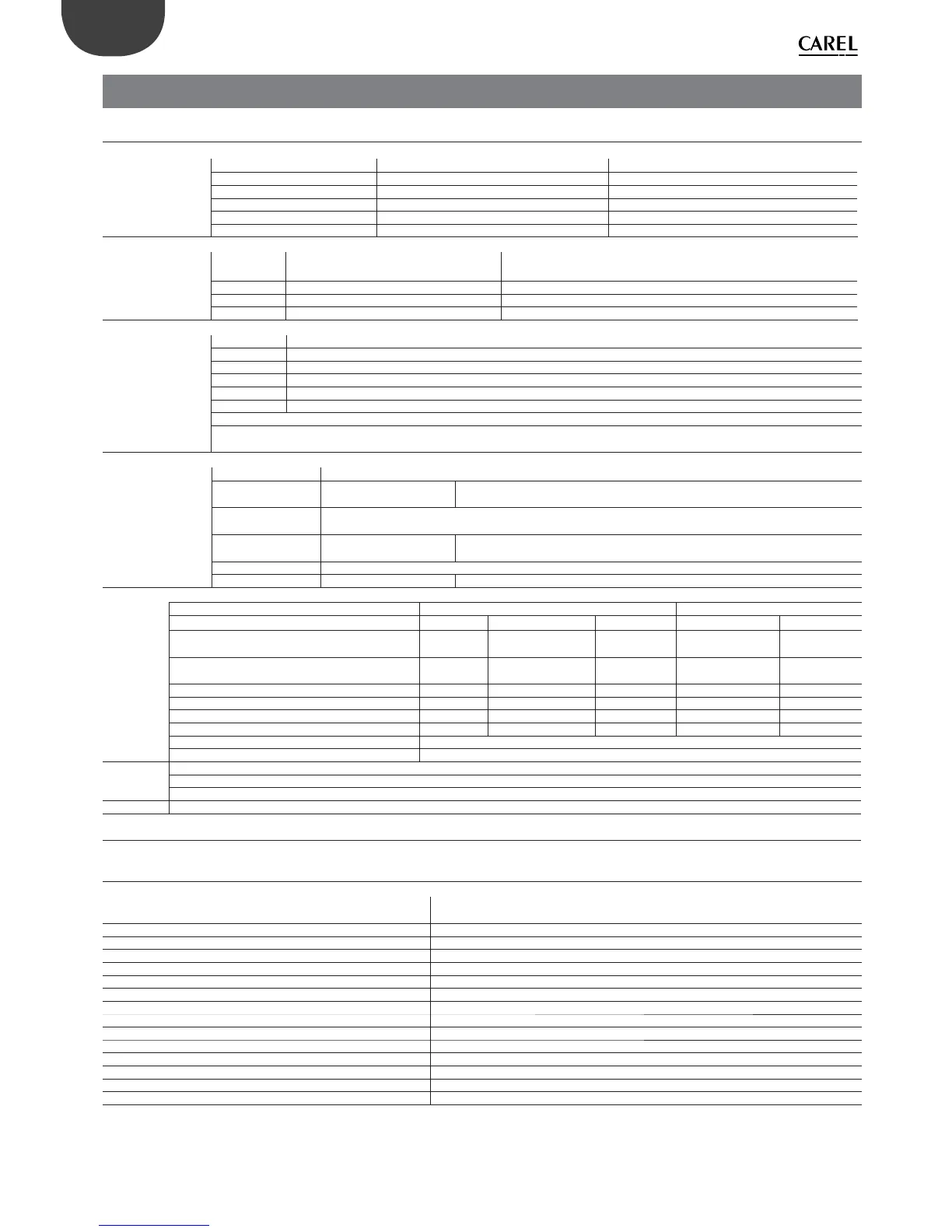
Power supply Model Voltage Power
IREVxxExxxx 230 V~, 50/60 Hz 3 VA, 25mA ~ max
IREVxxAxxxx 115 V~, 50/60 Hz 3 VA, 50mA ~ max
IREVxxHxxxx 115/230 V~, 50/60 Hz 6 VA, 50mA ~ max
IREVxxLxxxx 12 to 24 V ~, 50/60 Hz, 12/30 Vdc 3 VA, 300 mA ~/ mAdc max
IREVxx0xxxx 12 V ~, 50/60 Hz, 12/18 Vdc Only use SELV power supply
Insulation guaranteed
by the power supply
IREVxxExxxx
IREVxxAxxxx
insulation from extra low voltage parts reinforced, 6 mm clearance, 8 mm creepage, 3750V insulation
IREVxxHxxxx insulation from relay outputs basic, 3 mm clearance, 4 mm creepage, 1250V insulation
IREVxxLxxxx insulation from extra low voltage parts to be guaranteed externally by safety transformer (SELV)
IREVxx0xxxx insulation from relay outputs reinforced, 6 mm clearance, 8 mm creepage, 3750 V insulation
Inputs S1 (probe 1) NTC (IRxxx0xxxxx) or NTC and PTC (IRxxx7xxxxx)
S2 (probe 2) NTC (IRxxx0xxxxx) or NTC and PTC (IRxxx7xxxxx)
DI1 voltage-free contact, contact resistance < 10 , closing current 6 mA
S3 NTC (IRxxx0xxxxx) or NTC and PTC (IRxxx7xxxxx)
DI2 voltage-free contact, contact resistance < 10 , closing current 6 mA
S4 NTC (IRxxx0xxxxx) or NTC and PTC (IRxxx7xxxxx)
Maximum distance between probes and digital inputs less than 10 m
Note: in the installation it is recommended to separate the power and load connections from the probe, digital input, display and supervi-
sor cables.
Probe type Std. Carel NTC 10k at 25°C, range from –50T90°C
measurement error: 1°C in the range –50T50°C
3°C in the range +50T90°C
High temperature
NTC
50k at 25°C, range –40T150°C
measurement error: 1.5°C in the range –20T115°C
4°C in the range outside of -20T115°C
Standard Carel PTC 985 at 25°C, range from -50T150°C
measurement error 2°C in the range from –50T50°C4°C in the range from +50T150°C
Relay
outputs
depending on the model EN60730-1 UL 873
model relay 250 V~ operating cycles 250 V~ operating cycles
IRxxxx(E,A)(P,Q,S,U,V,X,Y,Z)xxx R2(*) 5 (1) A 100000 5 A res 1 FLA
6 LRA C300
30000
IRxxxx(E,A)(N, R, C, B,A,M,L, T)xxx R3(*) 5 (1) A 100000 5 A res 1 FLA
6 LRA C300
30000
IRxxxx(E,A)(N, R, C, B, A, M, L, T)xxx R1, R2 8 (4)A N.O. 6(4) A N.C. 100000 8 A res 2 FLA 30000
IRxxxx(0, L, H)(N, R, C, B, A, M, L, T)xxx R2, R3, R4 (*) 2(2) A N.O./N.C. 12 LRA C300
IRxxxx(E,A)(P, Q, S, U, V, X, Y, Z)xxx R1 12 (2)A N.O./ N.C. 100000 12 A res 5 FLA 30000
IRxxxx(0, L, H)(N, R, C, B, A, M, L, T)xxx R1 12 (2)A N.O./ N.C. 100000 30 LRA C300
insulation from extra low voltage parts reinforced, 6 mm clearance, 8 mm creepage, 3750 V insulation
insulation between independent relay outputs basic, 3 mm clearance, 4 mm creepage, 1250 V insulation
SSR outputs Max output voltage 12 Vdc
Output resistance 600
Max output current 20 mA
Connections Cable cross-section from 0.5 to 2.5 mm2 max current 12 A
(*): Relay not suitable for uorescent loads (neon lights, etc.) that use starters (ballasts) with phase shifting capacitors. Fluorescent lamps with electronic controllers
or without phase shifting capacitors can be used, depending on the operating limits speci ed for each type of relay.
The correct sizing of the power and connection cables between the instrument and the loads is the installer’s responsibility. Depending on the model, the maxi-
mum current at common terminals 1, 3 or 5 is 12 A. If using the controller at maximum operating temperature and at full load, the cables used must be suitable for
operation at least up to 105 °C.
Clock error at 25° C ±10 ppm (±5 min/year)
error at 25° C -10T60 °C -50 ppm (27 min/year)
Operating temperature -10T60 °C for all versions
Operating humidity < 90% RH non-condensing
Front panel ingress protection assembly on smooth and indeformable panel with IP65 gasket
Environmental pollution 2 (normal situation)
PTI of insulating materials printed circuits 250, plastic and insulating materials 175
Period of stress across the insulating parts long
Heat and re resistance category category D and category B (UL 94-V0)
Class of protection against voltage surge category II
Type of action and disconnection 1.B relay contacts (microswitching)
Construction of the control device built-in, electronic
Classi cation according to protection against electric shock class II when appropriately integrated
Maximum distance between interface and display 10 m
Programming key available on all models
Safety standards compliant with relevant European standards
Tab. 9.a

 Loading...


