27
E N G L I S H
µC
2
- +030220731 - rel. 1.2 - 26.10.2007
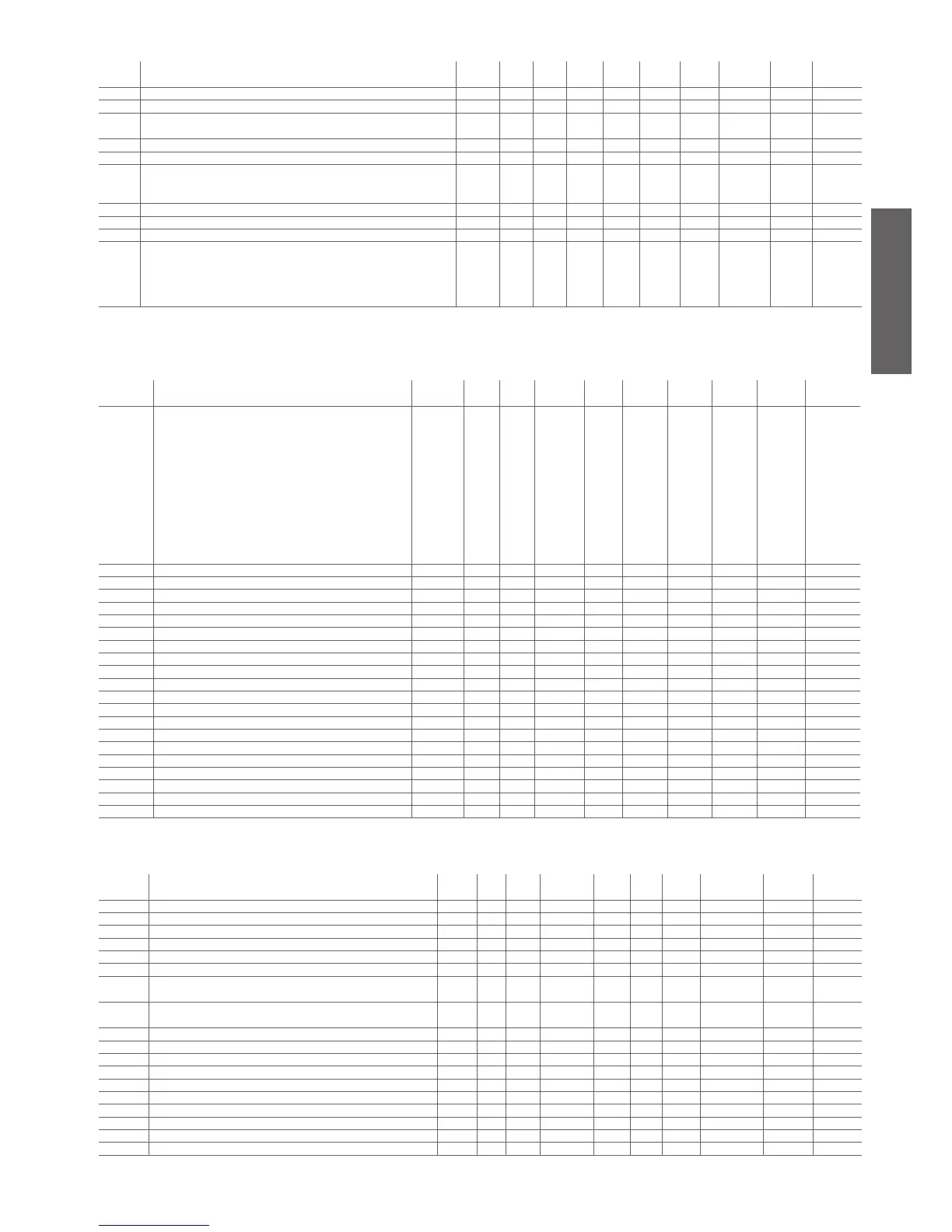
4.3.2 Antifreeze/auxiliary heater setting parameters (A*)
display
indicat.
parameter and description default
level
min. max. U.O.M. variat. default visibility supervis.
variable
Modbus variabile
type
A01 Antifreeze/low ambient temp. (air/air) alarm set point U A07 A04 °C/°F 0.1 3.0 - 11 (R/W) 11 Analog
A02 Differential for antifreeze/low ambient temperature alarm U 0.3 122.0 °C °F 0.1 5.0 - 12 (R/W) 12 Analog
A03
Bypass time for antifreeze alarm/low ambient temp. when turning on the unit
in heating mode
U 0 150 S 1 0 - 22 (R/W) 150 Integer
A04 Set point for the activation of antifreeze heater/auxiliary heater U A01 r16 °C/°F 0.1 5.0 - 13 (R/W) 13 Analog
A05 Diff. for antifreeze heater/auxiliary heater U 0.3 50.0 °C/°F 0.1 1.0 - 14 (R/W) 14 Analog
A06 Auxiliary heater probe
0= Control probe see (Table 5.a)
1= Antifreeze probe see (Table 5.a)
F 0 1 Flag 1 0 - 6 (R/W) 6 Digital
A07 Antifreeze alarm set point limit F -40.0 176.0 °C °F 0.1 -40.0 - 15 (R/W) 15 Analog
A08 Auxiliary heater set point in heating mode U A01 r16 °C °F 0.1 25.0 - 16 (R/W) 16 Analog
A09 Auxiliary heater differential in heating mode U 0.3 50.0 °C/°F 0.1 3.0 - 17 (R/W) 17 Analog
A10 Antifreeze automatic start up
0= disabled function
1= Heaters and pump on at the same time on A4/A8
2= Heaters and pump on indipendently on A4/A8
3= Heaters ON on A4/A8
U 0 3 Flag 1 0 - 23 (R/W) 151 Integer
Table 4.b
4.3.3 Probe reading parameters (B*)
display
indicat.
parameter and description default
level
min. max. U.O.M. variat. default visibility supervis.
variable
Modbus variabile
type
b00 Config. of probe to be shown on the display
0= probe B1
1= probe B2
2= probe B3
3= probe B4
4= probe B5
5= probe B6
6= probe B7
7= probe B8
8= set point without compensation
9= dynamic set point with possible compensation
10= remote ON/OFF digital input status
U 0 10 Flag 1 0 - 24 (R/W) 152 integer
b01 Value read by probe B1 D - - °C /°F - - - 70 (R) 70 Analog
b02 Value read by probe B2 D - - °C /°F - - - 71 (R) 71 Analog
b03 Value read by probe B3
D - - °C /°F - - - 72 (R) 72 Analog
b04 Value read by probe B4 D - - °C /°F/bar - - - 73 (R) 73 Analog
b05 Value read by probe B5 D - - °C /°F - - X 74 (R) 74 Analog
b06 Value read by probe B6 D - - °C /°F - - X 75 (R) 75 Analog
b07 Value read by probe B7 D - - °C /°F - - X 76 (R) 76 Analog
b08 Value read by probe B8 D - - °C /°F bar - - X 77 (R) 77 Analog
b09 Driver 1 evaporator temperature D - - °C /°F - - V 78 (R) 78 Analog
b10 Driver 1 evaporator pressure D - - bar - - V 79 (R) 79 Analog
b11 Driver 1 superheating D - - °C /°F - - V 80 (R) 80 Analog
b12 Driver 1 saturation temperature D - - °C /°F - - V 81 (R) 81 Analog
b13
Driver 1 valve position D 0 100.0 % - - V 82 (R) 82 Analog
b14 Driver 2 evaporator temperature D - - °C /°F - - XV 83 (R) 83 Analog
b15 Driver 2 evaporator pressure D - - bar - - XV 84 (R) 84 Analog
b16 Driver 2 superheating D - - °C /°F - - XV 85 (R) 85 Analog
b17 Driver 2 saturation temperature D - - °C /°F - - XV 86 (R) 86 Analog
b18 Driver 2 valve position D 0 100.0 % - - XV 87 (R) 87 Analog
b19 Temp. probe at the outlet of the external coil c1 D - - °C /°F - - V 88 (R) 88 Analog
b20 Temp. probe at the outlet of the external coil c12 D - - °C /°F - - XV 89 (R) 89 Analog
Table 4.c
4.3.4 Compressor setting parameters (c*)
display
indicat.
parameter and description default
level
min. max. U.O.M. variat. def. visibi-
lity
supervis.
variable
Modbus variabile
type
c01 Min. compressor ON time U 0 999 s 1 60 - 25 (R/W) 153 Integer
c02 Min. OFF time compressor U 0 999 s 1 60 - 26 (R/W) 154 Integer
c03
Delay between 2 starts of the same compressor U 0 999 s 1 360 - 27 (R/W) 155 Integer
c04 Delay between starts of the 2 compressors U 0 999 s 1 10 - 28 (R/W) 156 Integer
c05 Delay between 2 shut-downs of the 2 compressors U 0 999 s 1 0 - 29 (R/W) 157 Integer
c06 Delay at start-up U 0 999 s 1 0 - 30 (R/W) 158 Integer
c07 Delay in switching on the compressor after switching on the pump/inlet
fan (air/air)
U 0 150 s 1 20 - 31 (R/W) 159 Integer
c08 Delay in switching OFF the compressor after switching OFF the pump/
inlet fan (air/air)
U 0 150 min 1 1 - 32 (R/W) 160 Integer
c09 Maximum compressor operating time in tandem U 0 60 min 1 0 - 33 (R/W) 161 Integer
c10 Compressor 1 timer D 0 800.0 100 hours 0.1 0 - 90 (R) 90 Analog
c11 Compressor 2 timer D 0 800.0 100 hours 0.1 0 - 91 (R) 91 Analog
c12 Compressor 3 timer D 0 800.0 100 hours 0.1 0 - 92 (R) 92 Analog
c13
Compressor 4 timer D 0 800.0 100 hours 0.1 0 - 93 (R) 93 Analog
c14 Operation timer threshold U 0 100 100 hours 1 0 - 34 (R/W) 162 Integer
c15 Hour counter evaporator pump/fan 1 D 0 800.0 100 hours 0.1 0 - 94 (R) 94 Analog
c16 Hour counter condenser backup pump/fan 2 D 0 800.0 100 hours 0.1 0 - 95 (R) 95 Analog
c17 Minimum time between 2 pump starts U 1 150 min 1 30 - 35 (R/W) 163 Integer
c18 Minimum pump ON time U 1 15 min 1 3 - 36 (R/W) 164 Integer
Table 4.d

 Loading...


