28
E N G L I S H
µC
2
- +030220731 - rel. 1.2 - 26.10.2007
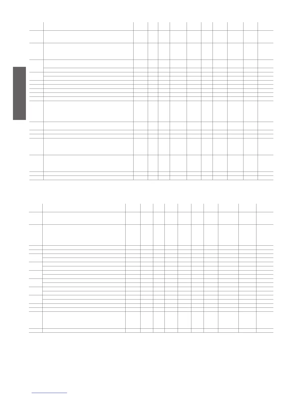
4.3.5 Defrost setting parameters (d*)
display
indicat.
parameter and description default
level
min. max. U.O.M. variat. def. visibility supervis.
variable
Modbus variabile
type
d01 Defrosting cycle/Condenser antifreeze
0= no;
1= sì, con sbrinamento unificato yes, with shared defrosting
U 0 1 Flag 1 0 - 7 (R/W) 7 Digital
d02 Time or temp.- press. based defrosting
0= time
1= temp. - press
2= pressure start, temperature end
U 0 2 Flag 1 0 D 90 (R/W) 218 Integer
d03
Start defrosting temperature
Condenser antifreeze alarm set point
U -40.0 d04 °C/°F 0.1 -5.0 DN 19 (R/W) 19 Analog
Start defrosting pressure /11 d04 bar 0.1 3.5 DP 18 (R/W) 18 Analog
d04
End defrosting temperature U d03 176 °C 0.1 20.0 DN 21 (R/W) 21 Analog
End defrosting pressure d03 /12 bar 0.1 14.0 DP 20 (R/W) 20 Analog
d05 Min. time to start a defrosting cycle U 10 150 s 1 10 D 37 (R/W) 165 Integer
d06 Min. duration of a defrosting cycle U 0 150 s 1 0 D 38 (R/W) 166 Integer
d07 Max. duration of a defrosting cycle U 1 150 min 1 5 D 39 (R/W) 167 Integer
d08 Delay between 2 defrosting cycle requests within the same circuit U 10 150 min 1 30 D 40 (R/W) 168 Integer
d09 Defrosting delay between the 2 circuits U 0 150 min 1 10 D 41 (R/W) 169 Integer
d10 Defrost by external contact
0= disables function
1= external contact start
2= external contact end
3= external contact start and end
F 0 3 Flag 1 0 D 42 (R/W) 170 Integer
d11 Antifreeze heaters activated while defrosting
0= Non presenti/Not present; 1= Presenti/Present
U 0 1 Flag 1 0 D 9 (R/W) 9 Digital
d12 Waiting time before defrosting F 0 3 min 1 0 D 43 (R/W) 171 Integer
d13
Waiting time after defrosting F 0 3 min 1 0 D 44 (R/W) 172 Integer
d14 End defrosting with 2 refrigerating circuits
0= Indipendent
1= If both at end defrost
2= If at least one at end defrost
F 0 2 Flag 1 0 D 45 (R/W) 173 Integer
d15 Start defrost with 2 circuits
0= Indipendent
1= If both at start defrost
2= If at least one at start defrost
F 0 2 Flag 1 0 D 46 (R/W) 174 Integer
d16 Forced ventilation time at the end of the defrosting F 0 360 s 1 0 D 47 (R/W) 175 Integer
d17 Defrost with compressors OFF F 0 80.0 °C/°F 0.1 0 D 22 (R/W) 22 Analog
Table 4.e
4.3.6 Fan setting parameters (F*)
display
indicat.
parameter and description default
level
min. max. U.O.M. variat. def. visibility supervis.
variable
Modbus variabile
type
F01 Fan output
0= absent
1= present
F 0 1 Flag 1 0 - 10 (R/W) 10 Diigital
F02 Fan operating mode
0= always ON
1= depending ON the compressor (in parallel operation mode)
2= depending ON the compressors in ON/OFF control
3= depending ON the compressors in speed control mode
U 0 3 Flag 1 0 F 48 (R/W) 176 Integer
F03
Min. voltage threshold for Triac F 0 F04 step 1 35 F 49 (R/W) 177 Integer
F04 Max. voltage threshold for Triac F F03 100 step 1 75 F 50 (R/W) 178 Integer
F05
Temp. value for min. speed Cooling U -40.0 °C 0.1 35.0 FN 24 (R/W) 24 Analog
Pressure value for min. speed Cooling /11 /12 bar 0.1 13.0 FP 23 (R/W) 23 Analog
F06
Differential value for max. speed Cooling U 0 50.0 °C/°F 0.1 10.0 FN 26 (R/W) 26 Analog
Differential pressure value for max. speed Cooling 0 50 bar 0.1 3.0 FP 25 (R/W) 25 Analog
F07
Fan shut-down differential in Cooling mode U 0 50.0 °C/°F 0.1 15.0 FN 28 (R/W) 28 Analog
Fan shut-down differential pressure in Cooling mode 0 F5 bar 0.1 5.0 FP 27 (R/W) 27 Analog
F08
Temperature value for max speed in Heating mode U -40.0 °C 0.1 35.0 FN 30 (R/W) 30 Analog
Pressure value for max speed in Heating /11 /12 bar 0.1 13.0 FP 29 (R/W) 29 Analog
F09
Differential temperature value for max. speed in Heating mode U 0 50.0 °C/°F 0.1 5.0 FN 32 (R/W) 32 Analog
Differential pressure value for max speed in Heating 0 F08 bar 0.1 4.0 FP 31 (R/W) 31 Analog
F10
Differential temperature to turn OFF the fan in Heating U 0 F08 °C/°F 0.1 5.0 FN 34 (R/W) 34 Analog
Differential pressure to turn OFF the fan in Heating 0 30.0 bar 0.1 3.0 FP 33 (R/W) 33 Analog
F11 Fan starting time U 0 120 s 1 0 F 51 (R/W) 179 Integer
F12 Triac impulse duration (fan start) F 0 10 s 1 2 F 52 (R/W) 180 Integer
F13
Fan management in defrost mode
0= Disabled fans
1= Fan in chiller mode
2= Max. speed after defrost
F 0 2 Flag 1 0 F 53 (R/W) 181 Integer
F14 Fan on time when starting in high condensing temperature U 0 999 S 1 0 FN 91 (R/W) 219 Integer
Table 4.f

 Loading...


