E N G L I S H
µC
2
- +030220731 - rel. 1.2 - 26.10.2007
- Antifreeze/low room temperature (air/air) alarm differential
A02: This represents the differential for the activation of the antifreeze alarm (low room temperature
in air/air units); the alarm condition cannot be reset until the temperature exceeds the set point +
differential (A01+A02).
- Antifreeze alarm bypass time low room temperature from unit start in heating mode
A03: This represents the delay in the activation of the antifreeze alarm when starting the system. In the
case of air/air units, this parameter represents the delay time for the low room temperature (return-intake
air) signal, only in heating mode. This means that the room being heated is too cold (threshold set by the
user).
- Antifreeze heater/auxiliary heater set point in cooling
A04: Determines the threshold below which the antifreeze heater is switched on. In the air/air units
(H01=0, 1) this parameter represents the temperature value below which the auxiliary heater is activated.
In the air/air heat pumps (H01=1) the auxiliary heaters are not used in cooling mode.
- Antifreeze heater/auxiliary heater differential
A05: Differential for the activation and deactivation of the antifreeze heaters (auxiliary heaters in air/air
units).
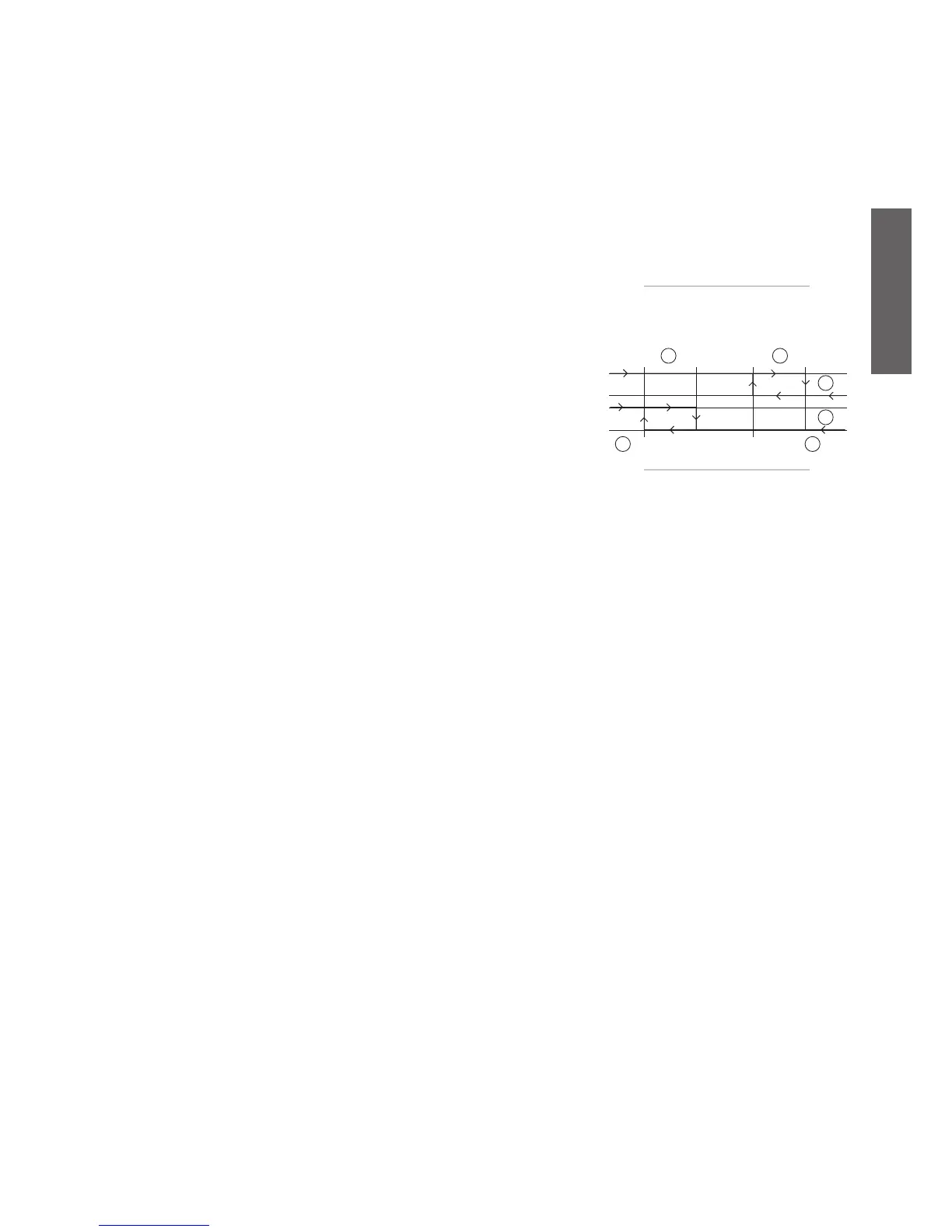
Operating diagram of the antifreeze alarm and the antifreeze heaters for air/water and water/water
chillers and heat pumps.
Key:
antifreeze alarm differen. (A2)
antifreeze heater differen (A5)
heaters
antifreeze alarm
antifreeze heater set point (A4)
antifreeze alarm set point (A1)
- Auxiliary heater probe in heating
A06: This determines which probe is used for control the auxiliary heater. The meaning of the parameter
is the following:
A06 = 0 => Control probe see Table 5.a.a
A06 = 1 => Antifreeze probe see Table 5.a.a
If H1=1 the heaters are disabled in cooling mode.
See Functions of the probes.
- Antifreeze alarm set point limit
A07: Establishes the minimum limit for setting the antifreeze alarm set point (A01).
- Antifreeze heater in defrost/auxiliary heater in heating set point
A08: Represents the threshold below which the auxiliary heater is ON in defrost and in heating mode.
In the heat pumps (H01=1-3-6), during heating mode, it represents the set point for the auxiliary heater;
during the defrost cycle, it represents the set point for the activation of the antifreeze heaters.
In the air/air units (H01=0) it only represents the set point for the heating heaters.
In heat pump mode (H1=5-10) this represents the set point for the antifreeze heater and the antifreeze
probe becomes B3/B7
- Antifreeze heater/auxiliary heater differential in heating
A09: Represents the differential for the activation/deactivation of the antifreeze heater in defrost/auxiliary
heater in heating.
- Automatic start for antifreeze
A10: This parameter is valid when the unit is in standby.
The operating mode switchover delay times are ignored.
A10=0: function not enabled
A10=1: Auxiliary heater and pump are ON at the same time, based to the respective set: points, A04
or A08, according to the settings of the antifreeze or auxiliary heaters; the exception is when H01=1 in
cooling, in which case not even the pump will be activated. Each circuit, in the case of two evaporators,
will be controlled based on its own probe (B2, B6).
A10=2: pump and auxiliary heater ON independently based on the respective set point, A04 or A08. If the
temperature falls below the antifreeze alarm set point A01, the unit is started in heating mode, controlling
the steps (compressors) based on the set point A01 and differential A02, in proportional mode. Each
circuit, when there are 2 evaporators, will be controlled using its own probe (B2, B6). A10=2: pump and
support heaters activated together, based on the set point A04.
This mode ends automatically when the antifreeze set point A01 + the differential A02 is reached
(returning to the previous mode); in any case, the function can be terminated manually by modifying the
parameters or disconnecting the power supply to the device.
In this case, the display will be as follows:
operating mode LED OFF;
cooling heating flag not switched (not detected by the supervisor);
antifreeze alarm A01 (remains active even at the end of the special operation if the unit was previously
ON, deactivated by manual reset or in standby).
A10=3: heaters ON based on the respective set point A04 and A08.
Do not use with H1= 6
1.
2.
3.
4.
5.
6.
•
•
•
•
CAREL NTC probes (mode H1= 2, 3, 4, 5 e 6)
Fig. 5.a.a

 Loading...


