E N G L I S H
µC
2
- +030220731 - rel. 1.2 - 26.10.2007
• Probe readings: parameters (B*)
- Select probe to be shown on display.
b00: Sets the probe reading to be displayed.
0= probe B1
1= probe B2
2= probe B3
3= probe B4
4= probe B5
5= probe B6
6= probe B7
7= probe B8
8= set point without compensation
9= dynamic set point with possible compensation
10= remote ON/OFF digital input status
For the list of parameter-probe associations see Table 4.d
Note: probes that are not present cannot be selected.
• Compressor settings: parameters (c*)
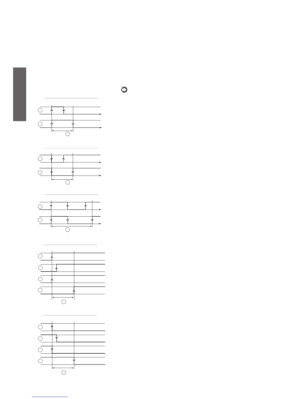
- Minimum ON time
c01: This establishes the time that the compressor must remain ON for when started, even if the stop
signal is sent.
Key:
1. signal;
2. compressor;
3. min. ON time-interval.
- Minimum OFF time
c02: This establishes the time that the compressor must remain OFF for when stopped, even if the start
signal is sent. The compressor LED flashes in this phase.
Key:
1. signal;
2. compressor;
3. min. OFF time-interval.
- Delay between 2 starts of the compressor
c03: This sets the minimum time that must elapse between two successive starts of the same compressor (deter-
mines the maximum number of starts per hour for the compressor). The compressor LED flashes in this phase. If
by mistake the user enters a value lower than the sum of C01 + C02, this parameter will be ignored and only the
times C01 and C02 will be considered.
Key:
1. signal;
2. compressor;
3. min. time-interval between two ON routins.
Fig. 5.a.b
Fig. 5.a.c
Fig. 5.a.d
Fig. 5.a.e
Fig. 5.a.f
- Start delay between compressors
c04: This sets the delay between the starts of the two compressors, so as to reduce the peak power input
and make the compressors start more smoothly. The compressor LED flashes in this phase.
In the event of capacity control, the delay c04 between compressor and valve becomes c04/2;
In the event of defrost operation, the delay between compressor and compressor is 3 seconds, and
between compressor and valve is 2 seconds.
Key:
1. 1
st
signal;
2. 2
nd
signal;
3. 1
st
compressore;
4. 2
nd
compressor;
5. time delay between two compressors ON routines/time-delay of the capacity-controlled routine.
- Stop delay between compressors
c05: This sets the stop delay between the compressors.
Legenda:
1. 2
nd
signal;
2. 1
st
signal;
3. 2
nd
compressor;
4. 1
st
compressore;
5. time delay between two compressors OFF routines/time-delay before the capacity-controlled routine.
•
•

 Loading...


