E N G L I S H
µC
2
- +030220731 - rel. 1.2 - 26.10.2007
- Delay on power-up (reset power supply)
c06: At power ON (when the controller is physically switched ON) the activation of all the outputs is delayed so
as to distribute the power input and protect the compressor against repeated starts in the event of frequent power
failures. This means that after the delay time, the controller will start to manage the outputs based on the other
times and the other normal functions.
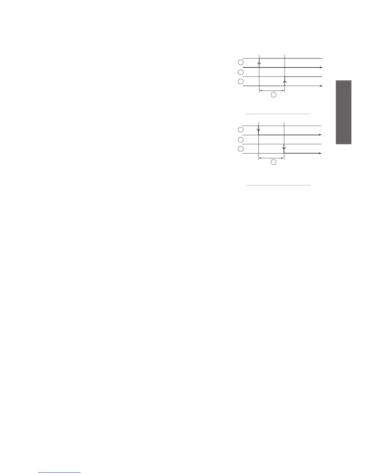
- Compressor start delay from pump/outlet fan (air/air) ON.
c07: In cooling and heating operation, if the operation of the pump (outlet fan) is subject to the controller (para-
meter H05=2), the compressor is started when required after the set time from the activation of the water pump
(or outlet fan in air/air units).
If the pump/outlet fan is always ON (H05=1) and consequently does not depend on the control logic, the com-
pressor is started after the set time from when the unit starts.
Key:
1. inlet fan;
2. pump;
3. compressor;
4. time-delay between pump-inlet fan and compressor.
- Pump/outlet fan (air/air) start delay from compressor OFF
c08: In cooling and heating operation, if the operation of the pump (outlet fan) is subject to the controller (para-
meter H05=2), when the compressor is requested to stop, the control first stops the compressor and the pump
(outlet fan).
If the pump/outlet fan is always ON (H05=1), it is only stopped in standby mode.
Key:
1. compressor;
2. pump;
3. inlet fan;
4. time-delay between pump-inlet fan and compressor.
- Maximum tandem compressor operating time
c09: In the case of two compressors in tandem per circuit, one compressor should not operate for longer than
the time set for c09 while the other compressor in the circuit is OFF. This prevents the oil shared in common
from migrating over the allowed limit towards the active compressor, and consequently avoids damage when
inactive compressor next starts (FIFO logic) due to poor lubrication. As a result, compressor 1 (or 2) in circuit 1, if
requested to operate continuously, will actually stop OFF after the time c09 and hand over to compressor 2 (or 1)
that was previously OFF.
This function always considers the compressor times. Any value lower than the time set for c03 will be ignored, and
the compressors (if the above condition is satisfied) will switch over after the time c03.
When C9=0, the function is disabled (the compressors will not switch over).
- Hour counter compressor 1-2-3-4
c10, c11, c12, c13: These indicate the number of operating hours of compressor 1, 2, 3, 4, expressed in
hundreds of hours.
Pressing p and q together, when the hour counter is displayed, resets the hour counter and, conse-
quently, cancels any maintenance requests in progress.
c10= operating hours comp. 1
c11= operating hours comp. 2
c12= operating hours comp. 3
c13= operating hours comp. 4
- Compressor operating hour counter threshold
c14: This sets the number of compressors operating hours, expressed in hundreds of hours, above which
the maintenance request signal is sent.
c14= 0: function disabled.
- Evaporator pump/fan 1 hour counter
c15: This indicates the number of operating hours for the evaporator
pump or fan 1, expressed in hundreds of hours.
Pressing p and q together, when the hour counter is displayed, resets the hour counter and, conse-
quently, cancels any maintenance requests in progress.
- Condenser or backup pump/fan 2 hour counter
c16: This indicates the number of operating hours for the condenser pump (or backup) or fan 2, expres-
sed in hundreds of hours.
Pressing p and q together, when the hour counter is displayed, resets the hour counter and, conse-
quently, cancels any maintenance requests in progress.
Fig. 5.a.g
Fig. 5.a.h

 Loading...


