E N G L I S H
µC
2
- +030220731 - rel. 1.2 - 26.10.2007
- Minimum OFF time before the next pump start
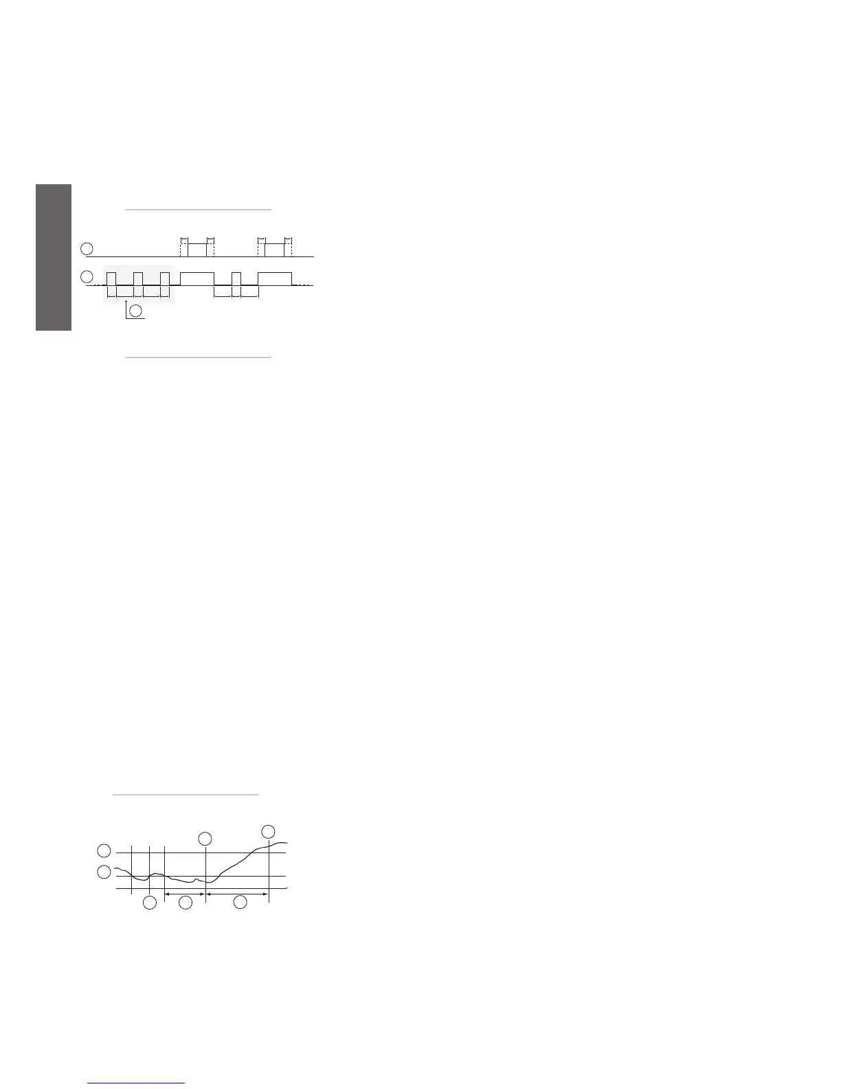
c17: The diagram below shows an example of the operation of the pump and with burst (active when
H05=3, see parameter H05).
The dashed areas on the compressor line indicate the pump-compressor and compressor-pump delay
times.
Burst mode is disabled in standby and during an alarm when the pump is OFF.
At power ON the delay c17 must elapse before burst can start.
- Minimum pump ON time
c18: This represents the minimum time that the pump remains ON for, see Fig. 5.i (active with H05=3
see parameter H05).
• Defrost settings: parameters (d*)
The defrost has priority over the compressor times.
For the defrost function the compressors times are ignored, with the exception of C04 (see C04 descrip-
tion for the exceptions).
Key:
1. compressor;
2. pump;
3. burst.
- Enable condenser defrost/antifreeze
d01: For heat pumps with air-cooled condensers (H01=1, 3, 8), this establishes whether defrost control must be
performed on the outdoor exchanger (evaporator in heating mode).
On the other hand, for water/water heat pumps with reversal on the gas circuit (H01=5-10), it enables antifreeze
control on the cooling water for the outdoor exchanger, which becomes the evaporator in heating mode, see d03.
If the fan is not present, the function is not enabled for air/water units.
d01=0: condenser defrost/antifreeze disabled;
d01=1: condenser defrost/antifreeze enabled.
If defrosting is enabled, the LED corresponding to the condensate symbol on the display will come O.
Fig. 5.a.i
Fig. 5.a.j
Temperature-based defrost (d2= 1)
- Type of defrost
d02: establishes the type of defrost.
d02=0: the defrost has a fixed duration that depends on 007
d02=1: the defrost starts and ends according to the temperature or pressure thresholds, see d03 and d04;
d02=2: the pressure transducer and temperature probe are both located on the outside exchanger; the defrost
starts when the value read by the pressure transducer is below the threshold d03 and ends when the value read by
the temperature probe is above the threshold d04; during the defrost, the pressure probe controls the fan speed,
as in chiller mode, so as to limit the pressure, even if the NTC probe, caked by ice, delays the end defrost. In any
case, after the maximum time allowed for the defrost, the unit will always exit the defrost procedure.
- Start defrost temperature/pressure or condenser antifreeze
alarm set point
d03: For heat pumps with air-cooled condensers (H01=1, 3, 8, 10, 12), this sets the temperature or
pressure below which the defrost cycle starts. To start the defrost cycle, the condition must be valid for
the time d05. For water/water heat pumps with reversal on the gas circuit (H01=5, 10), it defines the set
point for the activation of the antifreeze alarm for the outdoor exchanger cooling water (evaporator in
heating mode, on probe B3).
- End defrost temperature/pressure
d04: Establishes the temperature or pressure above which the defrost cycle ends.
- Minimum start defrost time
d05: Establishes the time that temperature/pressure must remain below the start defrost threshold d03,
while the compressor is ON, for the defrost cycle to be activated.
Key:
1. end defrost T/P ;
2. start defrostT/P;
3. start defrostT;
4. end defrost;
5. min. time-interval to start a def. cycle (d6);
6. min defrost interval (d5);
7. timer reset.

 Loading...


