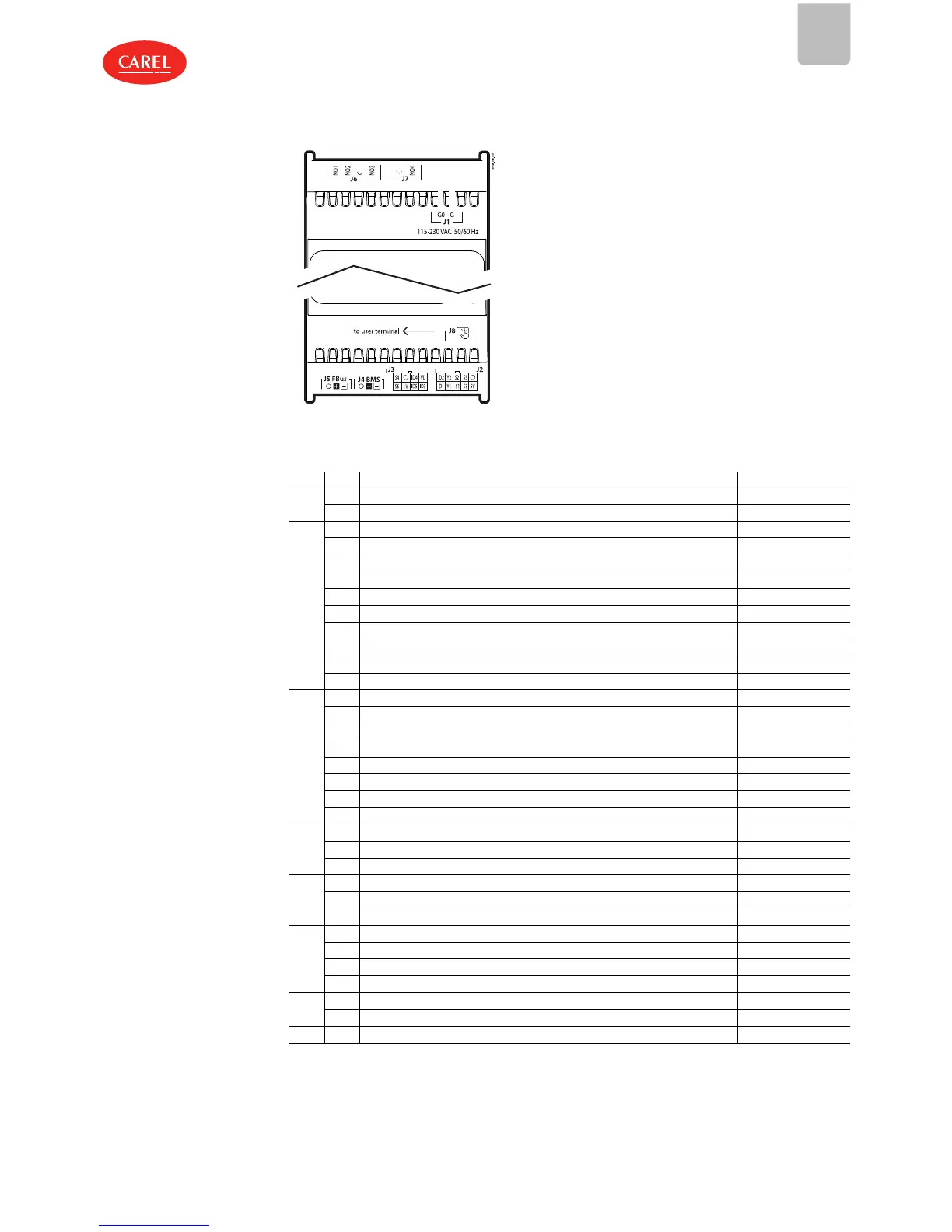
DIN rail model
Fig.2.h
Ref. Description Cable kit colour
J1
G Power supply -
G0 Power supply: reference -
J2
5V Ratiometric probe power supply white
S3 Analogue input 3 brown
S1 Analogue input 1 green
Y1 Analogue output 1 yellow
ID1 Digital input 1 grey
O GND: reference for probes, digital inputs and analogue outputs pink
S5 Analogue input 5 blue
S2 Analogue input 2 red
Y2 Analogue output 2 black
ID2 Digital input 2 purple
J3
ID3 Digital input 3 white
ID5 Digital input 5 brown
+V Power supply to 4-20 mA active probes green
S6 Analogue input 6 yellow
VL remote display power supply grey
ID4 Digital input 4 pink
O GND blue
S4 Analogue input 4 red
J4
- BMS serial port (RS485): Rx/Tx-
+ BMS serial port (RS485): Rx/Tx+
O BMS serial port (RS485): GND
J5
- Fieldbus serial port (RS485): Rx/Tx -
+ Fieldbus serial port (RS485): Rx/Tx +
O Fieldbus serial port (RS485): GND
J6
C Common for relays 1, 2, 3
NO1 Digital output (relay) 1
NO2 Digital output (relay) 2
NO3 Digital output (relay) 3
J7
C Common for relay 4
NO4 Digital output (relay) 4
J8 - Remote terminal connector (DIN version only)
Tab.2.a

 Loading...