4.4.4 Collegamento delle sonde di pressione raziometriche 0/5 V
Al pCO
1
possono essere
collegate tutte le sonde attive
di pressione della serie SPKT
Carel o qualsiasi sensore di
pressione presente sul mercato
con segnale 0/5 V raziometrico.
Gli ingressi che possono
accettare questi sensori sono:
B1, B2, B3 e B4, previa
configurazione da programma
applicativo e dai dip-switch
relativi sulla scheda.
Di seguito viene illustrato lo
schema di collegamento e la
corretta posizione dei
dip-switch:
morsetto pCO
1
colore cavetto sonda descrizione
+ 5 V ref nero alimentazione
GND verde riferimento alimentazione
B1, B2, B3, B4 bianco segnale
Tab. 4.4.4.1
4.4.5 Collegamento degli ingressi analogici selezionati come
ON/OFF
Il pCO
1
permette di configurare alcuni ingressi analogici come ingressi
digitali puliti. Gli ingressi che possono accettare questi sensori sono
B5, B6, previa configurazione da programma applicativo e dai
dip-switch relativi sulla scheda. Di seguito viene illustrato lo schema di
collegamento e la corretta posizione del dip-swtich.
AVVERTENZE: Il valore della corrente massima erogabile dall'ingresso
digitale è pari a 5 mA (quindi la portata del contatto esterno deve
essere almeno pari a 5 mA). Questi ingressi non sono optoisolati.
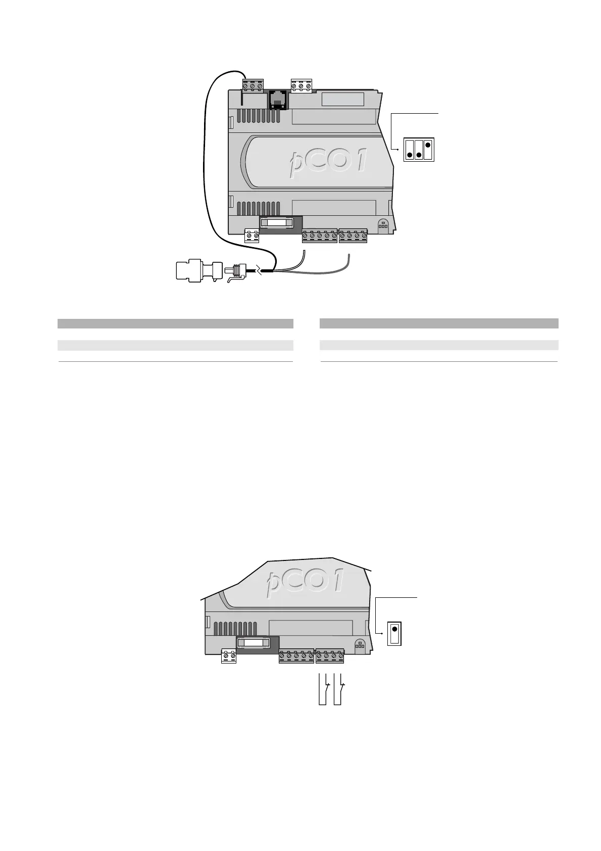
4.4.4 Connecting 0/5V ratiometric pressure probes
The pCO
1
can be connected to
all the Carel SPKT series active
probes pressure or any other
pressure sensor available on the
market with an 0/5V ratiometric
signal.The following inputs can
accept these sensors: B1, B2,
B3 and B4, after having
configured the program and the
corresponding dipswitches on
the board.
The connection diagram and the
correct position of the
dipswitches are shown below:
pCO
1
terminal probe wire colour description
+ 5V ref black power supply
GND green power supply ground
B1, B2, B3, B4 white signal
Table 4.4.4.1
4.4.5 Connecting the analogue inputs selected as ON/OFF
The pCO
1
allows some analogue inputs to be configured as
voltage-free digital inputs.The following inputs can be used: B5, B6,
after having configured the program and the corresponding dipswitches
on the board.The connection diagram and the correct position of the
dipswitches are shown below.
WARNINGS: The maximum current available at the digital input is 5mA
(thus the rating of the external contact must be at least 5mA).These
inputs are not optically-isolated.
23
pCO
1
manual - cod. +030221840 rel. 1.0 - 09/07/02

 Loading...


