Installation & Maintenance Manual
40
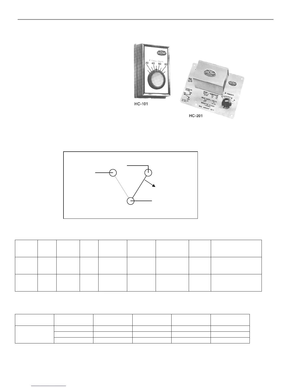
14.2. HC-101 and HC-201 Wall and Duct Humidistats
Mounting the HC-101 room humidistat: Mount
the HC-101 humidistat to an inside wall or post in
the area to be humidified. Position it so that no
drafts from registers or outlets are blowing on it.
Be sure that it is not placed over a device that
could generate heat or vapor ie: stove,
machinery, cleaning vat. The unit has three wire
leads, Orange, Brown and Red. Use the Orange
and Brown leads for control operation. Use the
Orange and Red leads for hi-limit operation.
Mounting the HC-201 duct humidistat: Cut a hole in the side of the duct and mount the HC-201 humidistat to the
duct, using the screws provided, at least 6 feet down stream of any live steam or mist. The unit has three wire leads,
Orange, Brown and Red. Use the Orange and Brown leads for hi-limit operation.
Wiring Diagram
TABLE 1. SPECIFICATIONS
Part
No.
Type Scale
Range
%RH
Diff.
%RH
Operating
Limits
°F (°C)
Shipping
& Storage
°F (°C)
Connection Cover Dimensions
In. (mm)
HC-101
Wall 10 to 90 5 40 to 125
(4 to 2)
-40 to 140
(-40 to 60)
6" (150 mm)
color coded
leads
Beige
plastic
4-3/8 x 2-7/8 x 1-5/8
(111 x 73 x 41)
HC-201
Duct 15 to 95 5 40 to 125
(4 to 2)
-40 to 140
(-40 to 60)
Coded
screw
terminals
Metal 4-3/4 x 6-1/2 x 2-1/4
(121 x 165 x 57)
TABLE 2. MAXIMUM ELECTRICAL RATINGS
Part No. AC Volt
50/60 Hz
FLA LRA Resistive
Amps
Pilot Duty
VA
24 - - 8 60
120 7.2 43.2 8 345
HC-101
HC-201
240 3.6 21.6 8 345
Brown (N.O.)
Red (N.C.)
Brown makes on Drop in R.H.
drop in humidity
Orange
Common
 Loading...


