SD Carel USA
41
14.3. PC-301 Air Proving Switch
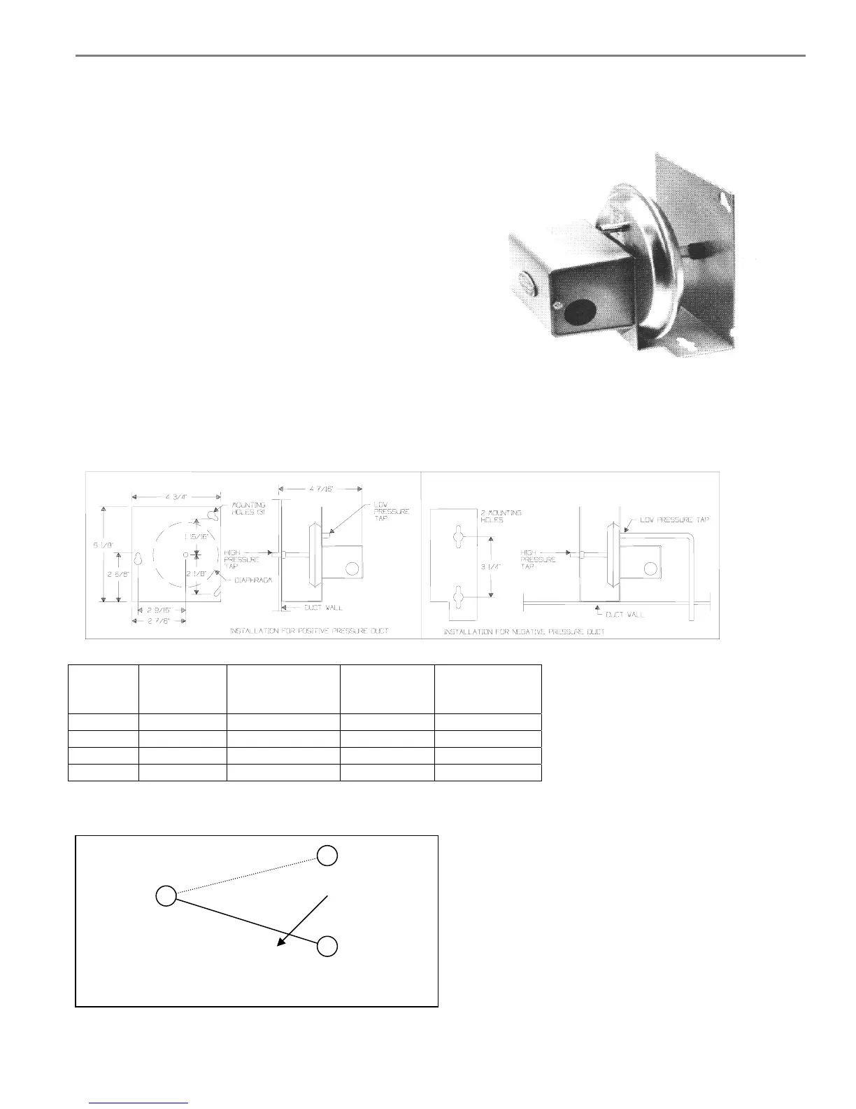
Mounting the PC-301 air flow switch:
Mount the airflow switch in the supply or return duct using the
screws supplied. Mount the device so that the diaphragm is in
a vertical position as shown at right.
If the airflow switch is to be mounted on the return duct
(vacuum), then mount it in a vertical position by the small
plate. Drill a 7/16" hole in the side of the duct and connect the
supplied tubing to the low pressure tap on the airflow switch
and then run it through the drilled hole in the duct. Put no more
than 2" of tubing into the duct. Caulk around the tubing where
it enters the duct. The high pressure tap is left open to
atmosphere.
If the airflow switch is to be mounted to the supply duct
(pressure), then simply drill a 7/16 hole in the side of the duct, apply caulking to the large plate, and mount the device
with the large plate to the duct and the high pressure tap/tubing mated the hole. The low pressure tap is left open to
atmosphere.
MOUNTING DIAGRAMS
TABLE 1. MAXIMUM ELECTRICAL SWITCH RATINGS
Vac Full Load
Amps
Locked Rotor
Amps
Pilot Duty
(VA)
Non-
Inductive
Amps
24V - - 60 10
120V 6.25 37.5 300 10
240V 3.1 18.6 300 10
277V 2.7 16.2 300 10
WIRING DIAGRAM
N.C.
Common Increase
Pressure
N.O. makes on increase N.O.
in pressure.
 Loading...


