EasyManua.ls Logo

Carel thTx - User Manual

Carel thTx
64 pages
Go to English
Print Icon
To Next Page IconTo Next Page
Loading...
High Efficiency Solutions
Manuale d’uso
User manual
Mode d’emploi
Technisches Handbuch
Manual del usuario
thTx
El
ectronic controller for air conditioning
Question and Answer IconNeed help?

Do you have a question about the Carel thTx and is the answer not in the manual?

Overview

The CAREL thTx is an electronic controller designed for air conditioning in residential and commercial environments, offering a user-friendly interface for temperature control. Its compact and elegant design makes it suitable for various settings. The thTx can function as a standalone room thermostat or as a zone controller when connected to programmable controllers in radiant heating systems. Depending on the model, it can be equipped with a temperature sensor or a combined temperature and humidity sensor, and supports power supply options of 230 Vac or 24 Vac/Vdc. The thTx also provides the ability to manage a three-speed fan.

Function Description

The thTx controller allows for easy and intuitive temperature adjustment using capacitive touch buttons. It is ideal for use as a Human-Machine Interface (HMI) for heat pumps, rooftop units, air handling units (AHUs), fan coils, and as a display for zone control in centralized systems. The RS485 serial connection, using the Modbus protocol, enables multiple thTx controllers to be connected to a central controller for synergistic operation with programmable controllers.

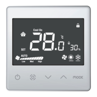
The device features a display with capacitive keys for interaction. The main functions include:

  • ON/OFF Button: Press and hold for a few seconds to switch the thermostat on or off. When off, all outputs are open.
  • Fan/Confirm Button: When the thermostat is running, press to adjust the fan speed (Low → Medium → High → Automatic → Off). Within menus or for SET configuration, this acts as the "confirm" button.
  • Up/Down Arrows: When the thermostat is running, press Up or Down to increase or decrease the target temperature by 0.5-degree increments. After adjustment, press Fan/Confirm to save the temperature or wait 8 seconds for automatic saving. When the thermostat is in normal operation, pressing both Up and Down arrows simultaneously for 3 seconds locks the display, showing a padlock icon. Pressing them again unlocks the display.
  • MODE Button: Press to cycle through the desired operating modes: Cooling, Heating, and Ventilation.

Usage Features

The thTx terminal allows for parameter and output configuration in two ways: directly via the terminal (using buttons and parameters) or via Modbus (using Modbus parameters).

Parameter Configuration: To access the parameter menu, switch off the thermostat using the ON/OFF button, then press and hold "MODE" + "Up Arrow" for 5 seconds. Enter the password (0022). The password can be changed using parameter E23.

Mode Selection: Pressing the Mode button cycles the lower-left icon through Heating (sun), Cooling (snowflake), and Ventilation (fan). The current mode can also be viewed via Modbus parameter HR140.

SET/FAN Button: This button allows changing the fan speed and, consequently, the three-speed fan output (EL/EM/EH). It also serves as the confirmation button for settings (setpoint and within the configuration menu). Pressing the button allows selecting the desired speed (low, medium, high) or automatic (Auto) and sending this information via Modbus (register 141).

Thermostat ON/OFF: The thermostat's ON/OFF state is managed either by the thermostat itself or via Modbus. To turn on, press "Up Arrow"; to turn off, press "Up Arrow" again to deactivate the relay. The ON/OFF state is controlled via Modbus register HR143 (0 = OFF; 1 = ON).

Buzzer Activation: Access menu E4 (Buzzer activation) and confirm: 0 = Disabled; 1 = Enabled.

Keypad Lock: In normal operation, pressing both Up and Down arrows simultaneously for 3 seconds locks the display, showing a padlock icon. This can also be configured via Modbus using variable HR165.

Relay Control: Relay control is available in both cooling and heating modes and is user-managed. The differential parameter (dF) in the parameter menu defines the differential for heating or cooling modes. The user must define the setpoint. In addition to cooling and heating management, the relay can be controlled for humidity via configuration menu E28.

Setpoint: Turn on the thermostat, use the Up arrow to increase the setpoint, or the Down arrow to decrease it by 0.5 degrees at a time. It can also be modified via Modbus HR144. The maximum and minimum setpoint values can be linked via HR145 and HR146, and their corresponding menus E6 and E7. The same applies when the relay is configured for humidity management, where the setpoint value adjusts by 1 RH% and is set via Modbus/HR134.

Differential: To adjust the temperature differential, access menu E19; for humidity, access menu E21. The temperature differential (HR58) increases by 0.1 from 0.0 to 5.0. The humidity differential (HR50) increases by 1 from 0 to 20.

Humidity Control: In models with a humidity sensor, the data is displayed next to the temperature value. The relative humidity value can also be read via Modbus register HR134.

Antifreeze Mode: This can be enabled via menu E10. Antifreeze is only valid in heating mode. When the temperature drops to 5.0°C, antifreeze activates; when it rises above 8.0°C, antifreeze protection stops by acting on the relay.

Alarm: When an alarm occurs, the corresponding error code is displayed on the LCD. Modbus Coil 32 takes the value 1. "E1" indicates a temperature sensor error, and "E3" indicates a humidity sensor error.

Temperature Sensor Calibration: To adjust temperature calibration, access menu E8 (temperature calibration) within a range of -9 to +9°C, with increments of ±0.1°C. This can also be configured via Modbus using variable HR10.

Humidity Sensor Calibration: Available only on models with a humidity sensor. To adjust humidity calibration, access menu E9 (humidity calibration) within a range of -20 to +20 RH%, with increments of ±0.1 RH%. This can also be configured via Modbus using variable HR57.

Manual Mode: In addition to the autonomous mode where thTx automatically regulates outputs based on setpoint values and configuration, the display can be used to manually override and manage icons and outputs via Modbus. This involves configuring Modbus parameters:

  • Coil 51: Manually configure relay state (0=Automatic, thTx; 1=Manual, via Modbus).
  • Coil 59: Manually configure Mode (0=Automatic, thTx; 1=Manual, via Modbus).
  • Coil 60: Manually configure Fan (0=Automatic, thTx; 1=Manual, via Modbus).

Display Icon Management: In default configuration, thTx can switch between Heating/Cooling/Ventilation. Via configuration menu E12 or Modbus register HR350, specific icons can be forced to display.

  • 0: Fan operates and is visible in both heating and cooling modes.
  • 1: Fan operates in heating mode and is not visible in cooling mode.
  • 2: Fan is visible in neither heating nor cooling mode, but fan mode can be selected.
  • 3: Only heating and cooling modes are available (fan mode not visible).
  • 0x255: NO ACTIONS (all icons suppressed); thTx operates as an ambient sensor.

Relay Management: By changing Coil 51 (Modbus RS485 "Relay management configuration"), icon 2 appears at the top left of the screen. Depending on the configuration via Coil 70 (or menu E28) "Relay output management" (0: Temperature = temperature control; 1: Humidity = humidity control) and the active MODE (HR140), the relay state can be controlled via Coil 52.

Important Technical Specifications

  • Power Supply: 85-260 Vac 50/60 Hz or 24 Vac/Vdc (±10%).
  • Operating Conditions: 0-55°C, 10-95% RH non-condensing.
  • Storage Conditions: -20-70°C.
  • Environmental Pollution Degree: 2.
  • Overvoltage Category: II.
  • Ingress Protection: IP20.
  • Protection Against Electric Shock: Class II.
  • EMC Standards: EN 61000-6-1, EN 61000-6-3.
  • Safety Standards: EN 60730-1.
  • Temperature Measurement Accuracy: ±0.5°C.
  • Humidity Measurement Accuracy: ±5% RH.
  • Maximum Power Absorption: <1W.
  • Resistive Load: 0.7A.
  • Serial Interface: RS485 for communication with controllers. Uses shielded AWG 20 to 22 cable. Total network length not exceeding 500m. Power cable cross-section between 0.5mm² and 1.5mm². Up to 32 terminals can be connected. For extended networks, a 120 Ohm resistor should be inserted between A (RX/TX+) and B (RX/TX-) on the last device to avoid communication issues.
  • Communication Mode: Protocol type: RTU. Data bits: 8. Stop bits: 2. Parity: None. These are editable via menus E25 (stop bits) and E26 (parity) or Modbus variables HR340 and HR341.
  • BMS Transmission Speed: 0=19200 (default), 1=9600, 2=4800. Editable via Modbus variable HR250.

Maintenance Features

Installation Recommendations:

  • thTx room thermostats are designed for flush mounting in distribution boxes compliant with current standards.
  • Before any work on the thermostat, disconnect the power supply by operating the main switch in the electrical panel (OFF position). Then, remove the front part of the thermostat from the back part to make electrical connections.
  • Install the thermostat at approximately 1.5m above the floor, where it can measure the average room temperature. Avoid direct sunlight, coverings, or heat sources to prevent skewed temperature readings.

Flush Mounting Instructions:

  • Use a flush-mounting box with a minimum diameter of 65mm and a minimum depth of 35mm.
  • Separate the front part of the thTx thermostat from the back part using a screwdriver.
  • Make electrical connections according to the wiring diagram.
  • Fix the back part to the flush-mounting box with the two supplied screws.
  • Finally, correctly reposition the thTx thermostat and ensure it clicks into place.

Disassembly: Insert a screwdriver into the slot at the bottom and press outwards to extract the display.

General Notes:

  • Avoid installing the device in environments with:
    • Relative humidity exceeding specified values.
    • Strong vibrations or shocks.
    • Exposure to water splashes.
    • Exposure to aggressive or contaminating atmospheres (e.g., sulfur or ammonia gases, saline vapors, smoke) to prevent corrosion and/or oxidation.
    • Strong magnetic and/or radio frequency interference (e.g., near transmission antennas).
    • Exposure to direct sunlight or general atmospheric agents.
    • Wide and rapid fluctuations in ambient temperature.
    • Environments with explosive or flammable gas mixtures.
    • Dust exposure (formation of corrosive patina with possible oxidation and insulation reduction).
  • Wiring: Separate sensor and digital input cables from inductive load and power cables as much as possible to avoid electromagnetic interference. Never run power and signal cables in the same conduits (including those in the electrical panel).

Material Warranty: 2 years (from production date, excluding wear parts).

Type Approval: The quality and safety of CAREL INDUSTRIES Hq products are guaranteed by the ISO 9001 certification for design and production.

WEEE Information:

  • Electrical and Electronic Equipment (WEEE) must not be disposed of as household waste but collected separately for recycling, treatment, or disposal as required by law.
  • Users must deliver EEE at the end of its life, along with essential components, to WEEE collection points designated by local authorities. The directive also allows returning the device to the retailer when purchasing an equivalent new device (1:1 equivalence or 1:0 equivalence if no external dimension exceeds 25 cm).
  • This device may contain hazardous substances; improper use or disposal can have negative effects on human health and the environment.
  • The crossed-out wheeled bin symbol (Fig. 1) on the product or packaging indicates that the device must be collected separately at the end of its life.
  • If the EEE contains a battery (Fig. 2), it must be removed before disposal according to instructions in the user manual. Used batteries must be taken to appropriate separate collection centers as required by local regulations.
  • Illegal disposal of WEEE is subject to penalties under applicable local waste regulations.

Carel thTx Specifications

General IconGeneral
BrandCarel
ModelthTx
CategoryController
LanguageEnglish

Related product manuals