12
ENG
"manuale thTx" +0300141IE rel. 1.0 - 16.01.2024
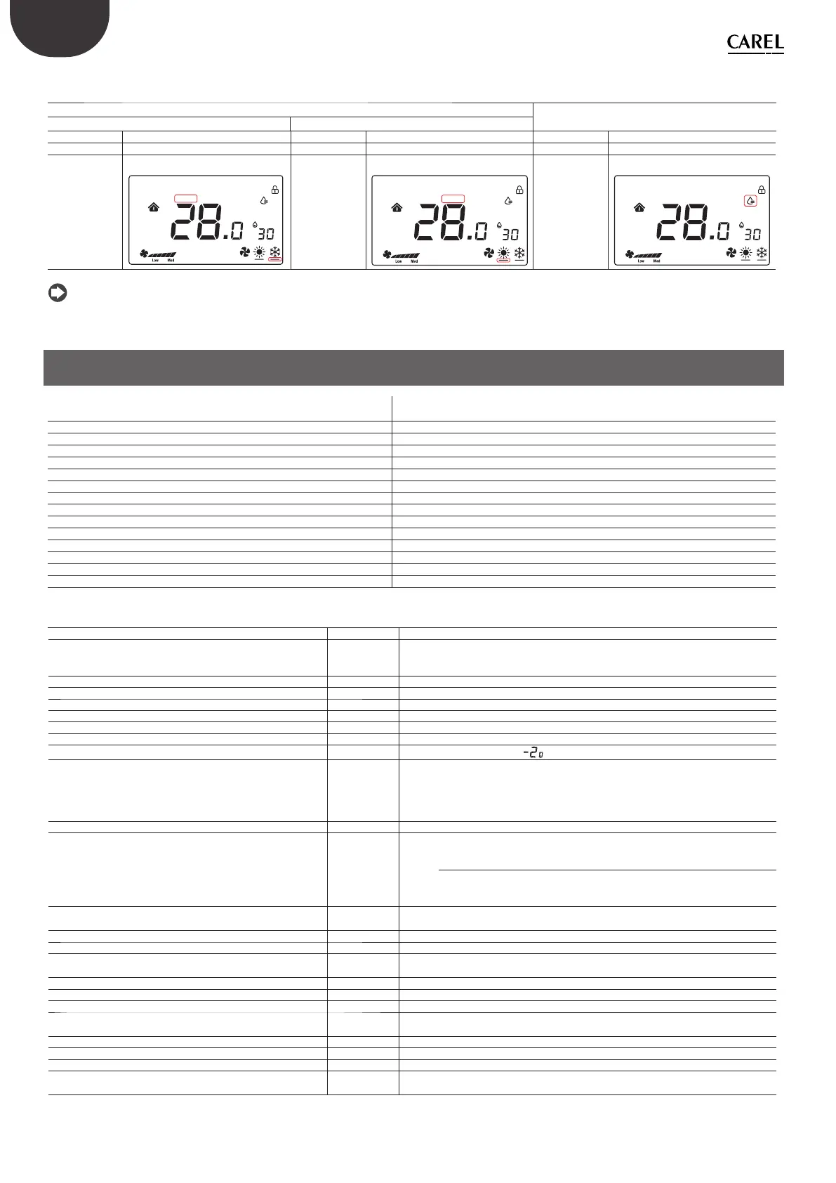
Summary of displays based on the confi guration:
Manual (Coil 51 =1)
Temperature (Coil 70 = 0)
Humidity (Coil 70 = 1)
Cool (HR140 = 3) Heat (HR140 = 4)
OFF ON OFF ON OFF ON
Relay OPEN Relay CLOSED Relay OPEN Relay CLOSED Relay OPEN Relay CLOSED
Cool On = OFF
Cool On = ON
Cool On Heat On
SET
1
2
3
4
°F °C
%
Heat On = OFF
Heat On = ON
Cool On Heat On
SET
1
2
3
4
°F °C
%
Water drop icon
= OFF
Water drop icon = ON
Cool On Heat On
SET
1
2
3
4
°F °C
%
Tab. 2.c
Notice: the confi gurations can be combined for complete control of the icons.
3. TECHNICAL SPECIFICATIONS
Power supply Models TDB*******: 85~260 VAC 50/60 Hz
Models TDC*******: 24 VAC/DC (+10 to -10%)
Operating conditions 0T55°C, 10 to <95% RH non-cond.
Storage conditions -20T60 °C
Environmental pollution 2
Software class and structure A
Casing ingress protection IP20
Heat and fi re resistance category UL94-V0
Class of protection against electric shock to be incorporated in class I or II appliances
Period of electrical stress across the insulating parts long
Immunity against surges Category III
Temperature measurement accuracy ±0.5 °C
Humidity measurement accuracy ±5% rH
Max power consumption < 1W
Resistive load ≤ 3A
Maximum load current 0.7 A
Tab. 3.a
No. Description Range Def. Notes
E01 Reset data to factory values 0÷99 53 Default: 53, set to 55 and select the MODE button
E02 Status after blackout 0÷ 2 1 0: the display is OFF.
1: the display shows the home screen.
2: the display shows the last status before the blackout.
E03 Backlight in standby 1 ÷5 4 -
E04 Buzzer 0÷1 0 0: Mute 1: On
E05 Communication address 1÷207 1 -
E06 Maximum temperature set point 0°C÷99°C 37°C -
E07 Minimum temperature set point 0°C÷99°C 5°C -
E08 Internal temperature calibration -9÷9 0.0 -
E09 Internal humidity calibration -20÷20 7
Notice: the display
shows -20°C not -2.0
E10 Frost protection ON/OFF OFF ON: Frost prot. On; 0F: Frost prot. Off
Range: 5.0°C to 8.0°C
Frost protection is only available during heating mode; when the temperature
drops to 5.0°C, frost protection is activated, while when the temperature is
above 8.0°C, frost protection is interrupted.
E11 Fan status when target temperature is reached ON/OFF OFF ON: Low speed 0F: Fan off
E12 Fan operating mode 0÷4 0 0: The fan operates and is visible in both heating and cooling modes
1: The fan operates in cooling mode but is not visible in heating mode
2: The fan operates in heating mode but is not visible in cooling mode
3: The fan is not visible in either heating or cooling mode, but the fan mode is
selectable
4: Heating and cooling modes only available (fan mode not visible)
E13 Fan circulation function option ON/OFF OFF ON: Low speed
OF: The fan is switched off
E14 Fan circulation time 1÷30 (Minutes) 5 (min) Set the fan circulation time per hour
E15 Temperature diff erential 0÷5 0.5
E16 Temperature unit of measure 0 ÷ 1 0 0: °C
1: °F
E17 Humidity diff erential 1%÷20% 5% -
E18 Maximum humidity set point 0%÷99% 70% -
E19 Minimum humidity set point 0%÷99% 50% -
E20 Serial port baud rate 0÷3 2 0= 4800 bps; 1= 9600 bps;
2= 19200 bps; 3= 38400 bps
E21 Serial port stop bits 0÷1 1 0 = 1 stop bit; 1 = 2 stop bits
E22 Serial port control bits 0÷2 0 0 = None; 1 = Odd; 2 = Even
E23 Change menu password 0000÷9999 0022 Range: 0000 to 9999
E24 Relay output control 0÷1 0 0: Temperature = Temperature control
1: Humidity = Humidity control
Tab. 3.b
Summary table of operating parameters