7
ENG
"manuale thTx" +0300141IE rel. 1.0 - 16.01.2024
1. GENERAL FEATURES
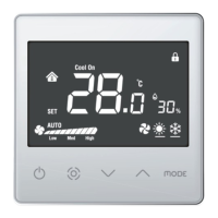
thTx is the CAREL room thermostat for residential or commercial
environments, off ering an easy-to-use interface.
The temperature is set simply and intuitively using the arrows on the
touch keypad. The compact dimensions and elegant design make it
suitable for any type of environment, as well as being ideal both as a user
interface (HMI) for heat pumps, rooftop units, AHUs, fan coils, etc., and as a
zone control display for centralised systems. The RS485 serial connection
via Modbus ® protocol can manage multiple thTx devices connected to
the same programmable controller, for synergistic control. The thermostat
can work in stand-alone mode as a room thermostat, or can be connected
to programmable controllers for zone management in radiant systems.
Depending on the model, it can be equipped with a temperature probe
or a temperature and humidity probe, and is available with 230 Vac or 24
Vac/Vdc power supply. thTx can also manage a three-speed fan.
1.1 Models
FLUSH MOUNTING part numbers:
P/N Model
TDB001AAF0 85-260 VAC, temperature sensor only
TDC001AAF0 24 VDC/AC, temperature sensor only
TDB001ACF0 85-260 VAC, temperature and humidity sensor
TDC001ACF0 24 VDC/AC, temperature and humidity sensor
Tab. 1.a
Fig. 1.a
1.2 Dimensions
Dimensions for fl ush mounting
86
86
46.8
32.7
14.1
49.06
45.56
Fig. 1.b
Rear dimensions (mm)
81.4
60
60
81.4
Fig. 1.c
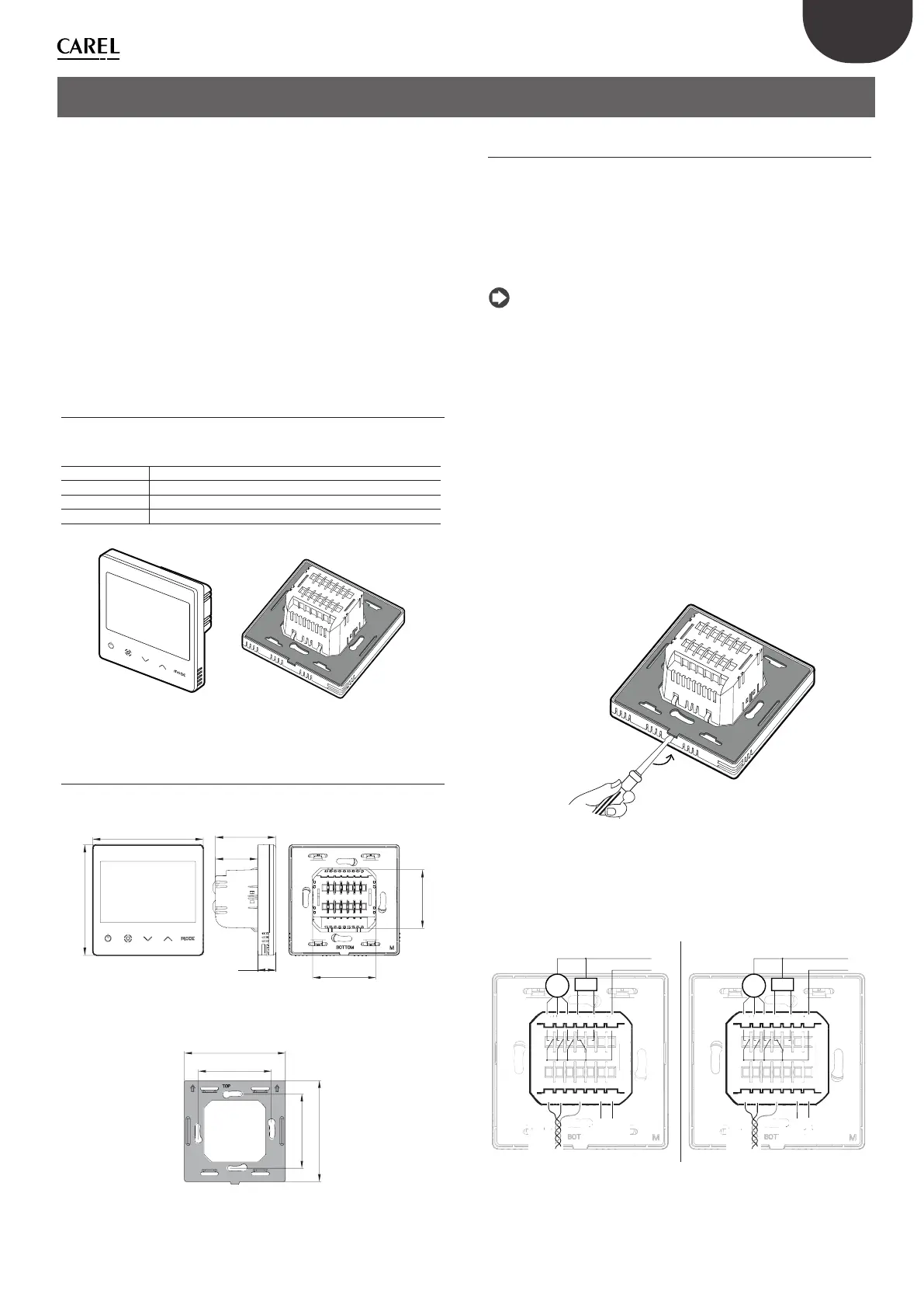
1.3 Assembly and connections
Installation warnings
• The thTx thermostats have been designed for fl ush mounting, in wall
boxes compatible with the standards in force;
• before carrying out any operations on the thermostat, disconnect the
device from the power supply using the main switch on the electrical
panel (OFF position). Then detach the front part of the thermostat from
the rear part to make the electrical connections.
Notice: the thermostat should be installed indoors, at a height of
approximately 1.5 m above the fl oor, in a place representing the average
room temperature. It should be away from direct sunlight, any coverings
or any heat source, to avoid false readings for temperature control.
Istruzioni per il montaggio a incasso
Per montare la parte posteriore del dispositivo, utilizzare una scatola ad
incasso di diametro minimo pari a 65 mm e con una profondità minima
di 35 mm.
1. Separare la parte anteriore del termostato thTx da quella posteriore
con un cacciavite;
2. Eff ettuare i collegamenti elettrici secondo lo schema;
3. Fissare la parte posteriore alla cassetta a incasso con le 2 viti in
dotazione:
4. Infi ne, riposizionare correttamente il termostato thTx nella posizione
originale, e assicurarsi tramite la pressione a scatto che si agganci
dopo il click.
Disassembly
Fig. 1.d
Electrical connections
230 V/230 V version
TDB001AAF0, TDB001ACF0
24 V/24 V version
TDC001AAF0, TDC001ACF0
EH EM
B (-)
A (+)
V+GV-
EL VC VO COM
M
Power
Power Supply
AC/DC 24V ±10%
Fan Valve
EH EM
B (-) A (+) LGN
EL VC VO COM
M
Power
Modbus
RS485
Modbus
RS485
Fan Valve
Power Supply
AC 85~265V
Fig. 1.e Fig. 1.f