8
ENG
"manuale thTx" +0300141IE rel. 1.0 - 16.01.2024
Serial interface
RS485 serial interface for communication with the controllers. Use AWG
20 to 22 shielded wire. The total length of the network must not exceed
500 m. The power supply wires must be between 0.5 mm
2
and 1.5 mm
2
.
Up to 32 terminals can be connected. For large networks, place a 120
Ohm resistor between A (RX/TX+) and B (RX/TX-) on the last device, to
avoid possible communication problems.
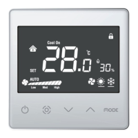
Exploded view
Fig. 1.g
Disassembly
Insert a screwdriver into the groove on the bottom and press outwards
to detach the display.
General notes
Avoid installing the device in environments with the following
characteristics:
• relative humidity higher than the specifi ed value;
• strong vibrations or knocks;
• exposure to water sprays;
• exposure to aggressive and polluting atmospheres (e.g.: sulphur and
ammonia gases, saline mist, smoke) which may cause corrosion and/
or oxidation;
• strong magnetic and/or radio frequency interference (thus avoid instal-
lation near transmitting antennae);
• exposure to direct sunlight and the elements in general;
• wide and rapid fl uctuations in room temperature;
• environments where explosives or fl ammable gas mixtures are present;
• exposure to dust (formation of corrosive patina with possible oxidation
and reduction of insulation).
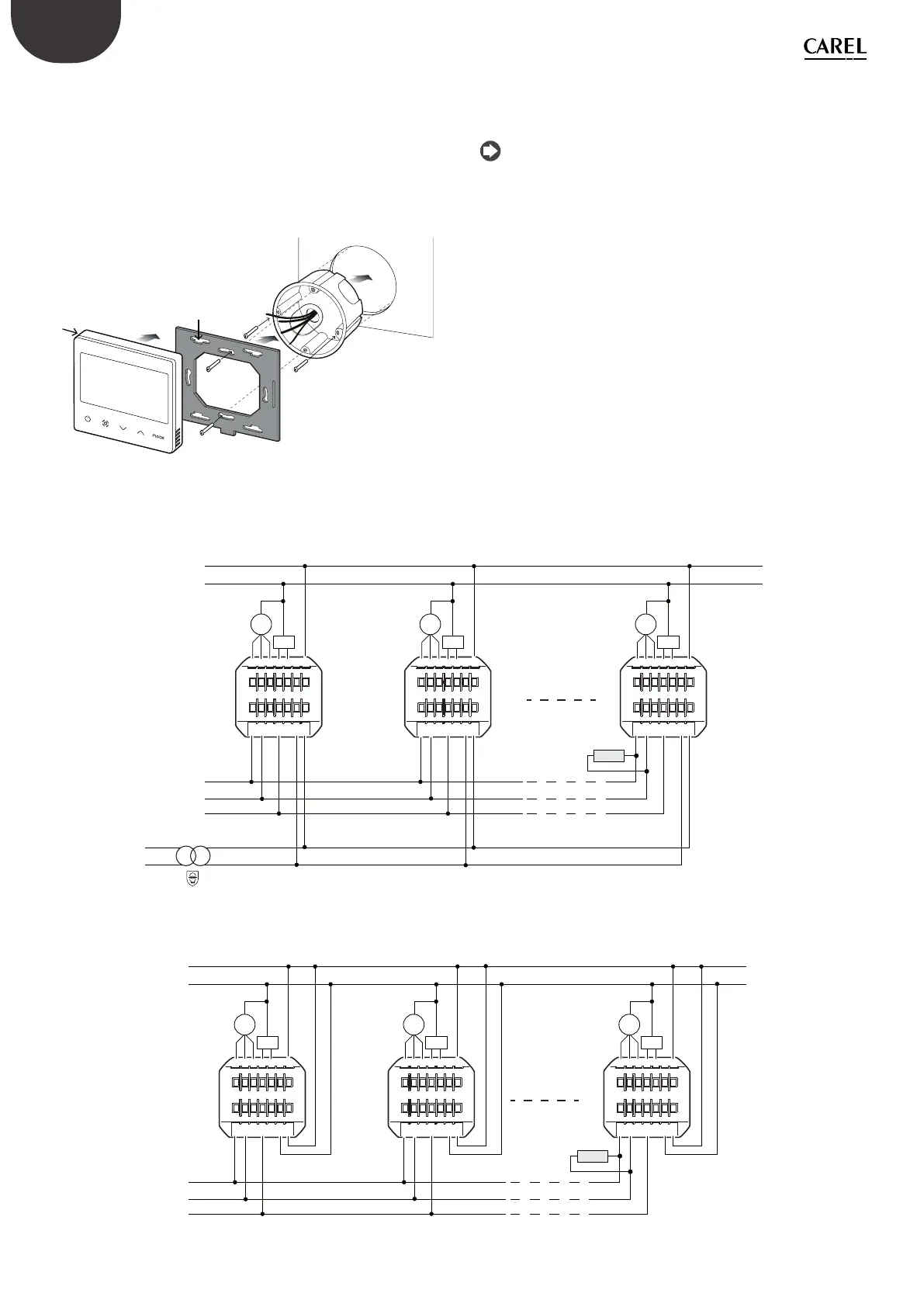
thTx 24 Vac/dc network confi guration
EH
B (-) A (+) G V -
V-
V+
V+
EM EL VC V0 COM
M
Fan
Valve
EH
B (-) A (+) G V - V +
EM EL VC V0 COM
M
Fan
Valve
EH
B (-) A (+) G V - V +
EM EL VC V0 COM
M
Fan
Valve
L
N
B (-)
A (+)
GND
thTx
n.1
thTx
n.2
thTx
n.32
120 Ω
230 Vac 24 Vac
Fig. 1.h
thTx 230 Vac network confi guration
EH
B (-) A (+) G N L
EM EL VC V0 COM
M
Fan
Valve
EH
B (-) A (+) G N L
EM EL VC V0 COM
M
Fan
Valve
EH
B (-) A (+) G N L
EM EL VC V0 COM
M
Fan
Valve
L
N
B (-)
A (+)
GND
thTx
n.1
thTx
n.2
thTx
n.32
120 Ω
Fig. 1.i