BT2 user manual - H-5911-9004-02-B Page | 46
Boretrak2 probe. Even numbers of metres are marked with red nodules, odd numbers with silver.
A brass cone connector is fastened to the end of the push rod. Screw the deployment adaptor into the brass cone
connector. The Boretrak2 probe can then be easily connected to the push rod.
The standard push rod has a cross sectional diameter of 9 mm. The minimum bend radius of the push rod is 30cm.
A brake lever on the side of the frame locks and unlocks the cage. Rotate the brake lever clockwise to tighten and
anti-clockwise to untighten the rotation of the cage. Release the brake to deploy the push rod.
WARNING: a large amount of energy is stored in the coiled fibreglass rod. Always maintain control
over the free end of the rod when the brake is not applied. Always keep the brake lever locked
when the push rod is not being deployed or recovered.
WARNING: do not exceed the minimum bend radius of the push rod.
For transportation, the push rod system is supplied dismantled. The frame must be assembled on receipt, before
the system is used on site.
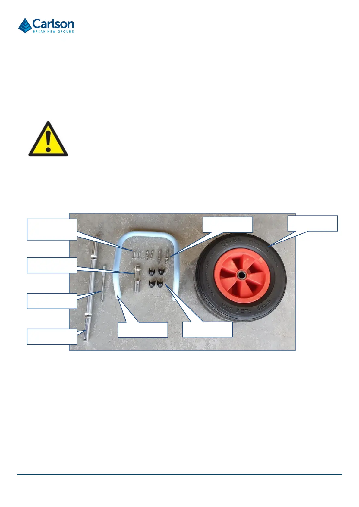
6.8.1 Supplied parts
The following parts are supplied as part of a push rod system.
• 1 x Push rod frame
• 1 x Frame handle
• 1 x Wheel axle
• 1 x Brake handle
• 1 x Cable guide
• 4 x Stud feet
• 2 x Clevis pins
Wheels
Wheel axle
Brake handle
Cable guide
Frame handle
Stud feet
Clevis pins
Nut, bolt and
washer sets
Figure 51 Push rod system - supplied parts