BT2 user manual - H-5911-9004-02-B Page | 51
To attach the optional stud feet to the frame, turn the frame on its side so it is resting on the handle. Attach the stud
feet to the frame through the 4 holes in the base of the frame. Use the M6 x 35 mm screws with washers. Tighten
the screws using the 5 mm hex key.
6.9 Boretrak rods (optional)
A series of hinged Boretrak rods may be used to push the probe in an uphole or horizontal deployment.
The rods are produced in 1 m lengths. The exception to this is the ‘lead’ rod which is 0.3 m long. This shorter rod
attaches directly to the probe. The length of the lead rod plus the probe is equal to 1 m.
Figure 61 Rod rack with rods and probe attached
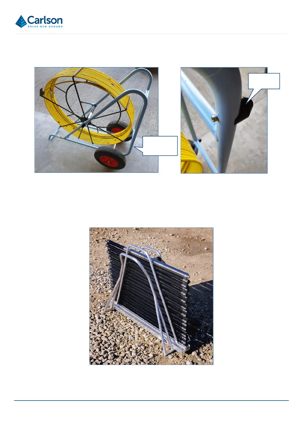
Stud feet
Holes in
frame base
Figure 60 Assembly of push rod frame - step 9