18
English
The 30AWH__H units are equipped with an integrated
hydronic module with a variable ows pump self-
controlled that allows fast installation with the aid of a few
external components. The 30AWH__X units, on the other
hand, do not have a circulation pump and expansion
vessel.
For this reason, they must be provided outside. In any case,
all the necessary protections and valves are to be inserted
in the water circuit inside the unit.
Refer to Figure 9 for the exact connection of the water
pipes. Figures 10 and 11 describe the integrated
components in their various con gurations.
NOTE: The correct dimensioning of the expansion vessel
is left to the installer as a function of the type of plant.
NOTE: The discharge of the safety valve can be
channelled to the outside of the machine using the
pre-cut holes (see Fig. 4). In this case, it is necessary to
provide an open drain funnel.
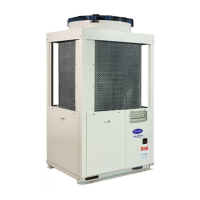
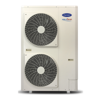
Size 004-006-008 Size 012-015
The operating red knob allows to set several pressure levels in 2 control modes :
-Variabledierentialpressure(Δp-v)
-Constantdierentialpressure(Δp-c)
The user interface allows to select between 6 pressure levels in 2 control modes:
- 3 constant pressure/power curves (CP)
- 3 proportional pressure curves (PP)
Min ow=1 ; Max ow=3
‘‘Set Up’’ procedure : ‘‘Set Up’’ procedure :
Factorypre-setting=Δp-c8.
Allfunctionscanbeset,activatedordeactivatedbyusingtheoperatingred
knob:
-ThecontrolmodeΔp-vissetontheleftofthemiddleposition(from1to8).
-ThecontrolmodeΔp-cissetontherightofthemiddleposition(from1to8).
-Forventingthepump,turntheknobinitsmiddleposition(theventing
function is activated after 3 seconds and lasts 10 minutes before going to
Δp-cmaxmode).
1) Factory pre-setting Constant Pressure Curve CP3
2) Push the button 10 sec Pump goes to setting mode - LED
startsashing
3) With each push the setting changes LED 1-2-3 shines / control curve and
mode is changing
4) After 10 sec not pushing the button Setting is adapted – pump goes back
to operation mode
5) LED 1 or 2 or 3 is permanently
shining
Pump is running with the selected
curve and mode
NOTE:
-Thevariablepressuremode(Δp-vorPP)isrecommendedinheatingsystemswithradiators.
-Theconstantpressuremode(Δp-corCP)isrecommendedforunderoor-heatingcircuits.
-Allhydroniccurves(Fig.14)havebeendenedinconstantpressuremodeformin,mediumandmaxspeed.
Variabledierentialpressure(Δp-v)
Constantdierentialpressure(Δp-c)
Venting function
PP1(ashingfast)
PP2(ashingfast)
PP3(ashingfast)
CP1(ashingslow)
CP2(ashingslow)
CP3(ashingslow)
 Loading...