38MGR-04SM Specifications subject to change without notice. 31
TROUBLESHOOTING
This section provides the required flow charts to troubleshoot
problems that may arise.
NOTE: Information required in the diagnoses can be found
either on the wiring diagrams or in the appendix.
Required Tools:
The following tools are needed when diagnosing the units:
• Digital multimeter
• Screw drivers (Phillips and straight head)
• Needle-nose pliers
• Refrigeration gauges
Recommended Steps
1. Refer to the diagnostic hierarchy charts below and determine the
problem at hand.
2. Go to the chart listed in the diagnostic hierarchy and follow the
steps in the chart for the selected problem.
For the ease of service, the systems are equipped with diagnostic code
display LED’s on both the indoor and outdoor units. The outdoor
diagnostic display is on the outdoor unit board and is limited to very
few errors. The indoor diagnostic display is a combination of flashing
LED’s on the display panel on the front of the unit. If possible always
check the diagnostic codes displayed on the indoor unit first.
Problems may occur that are not covered by a diagnostic code, but are
covered by the diagnostic flow charts. These problems are typical air
conditioning mechanical or electrical issues that can be corrected
using standard air conditioning repair techniques.
For problems requiring measurements at the control boards, note the
following:
1. Always disconnect the main power.
2. When possible check the outdoor board first.
3. Start by removing the outdoor unit top cover.
4. Reconnect the main power.
5. Probe the outdoor board inputs and outputs with a digital multi-
meter referring to the wiring diagrams.
6. Connect the red probe to hot signal and the black probe to the
ground or negative.
7. Note that some of the DC voltage signals are pulsating voltages for
signal. This pulse should be rapidly moving at all times when there
is a signal present.
8. If it is necessary to check the indoor unit board, you must start by
disconnecting the main power.
9. Remove the front cover of the unit and then control box cover.
10. Carefully remove the indoor board from the control box. Place it
face up on a plastic surface (not metal).
11. Reconnect the main power and repeat steps 5, 6, and 7.
12. Disconnect main power before reinstalling the board to avoid shock
hazard and board damage.
Outdoor Unit Digital Display
A digital display is featured on the outdoor PCB. The LED displays
different codes in the following situations:
• Standby: “- -”
• Compressor operation: the running frequency
• Defrosting mode: “dF” or alternative displays between running
frequency and “dF” (each appears for 0.5s)
• Compressor pre-heating: “PH” or alternative displays between
running frequency and “PH” (each appears for 0.5s)
• Oil return process: “RO” or alternative displays between running
frequency and “RO” (each appears for 0.5s)
• Low ambient cooling mode: “LC” or alternative displays between
running frequency and “LC” (each appears for 0.5s)
• Forced cooling mode: the LED displays “FC” or alternative
displays between running frequency and “FC” (each appears for
0.5s)
• PFC module protection occurs three times within 15 minutes: “E6”
or alternates between displays of running frequency and “E6”
(each appears for 0.5s)
• In protection or malfunction, the LED displays an error code or
protection code
Diagnostic Guides
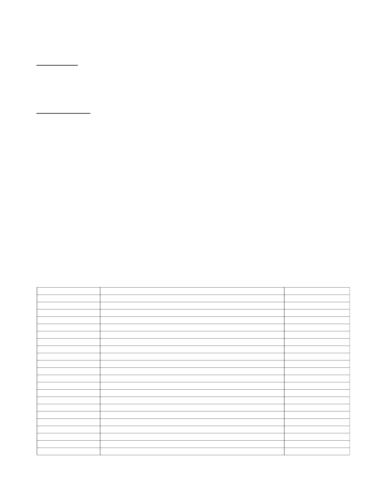
Table 31 — Outdoor Unit Error Display
OUTDOOR UNIT DISPLAY LED STATUS INDOOR UNIT DISPLAY
E0 Outdoor EEPROM malfunction F4
E2 Communication malfunction between indoor and outdoor units E1
E3 Communication malfunction between IPM board and outdoor main board — —
E4 Open or short circuit of outdoor temperature sensor (T3,T4,T5,T2B) F2/F1/F3/F6
E5 Voltage protection P1
E6 PFC module protection — —
E8 Outdoor fan speed has been out of control (Only for DC fan motor models) F5
E9 Wrong wiring connection of 24K indoor unit — —
F1 No A Indoor unit coil outlet temp. sensor or connector of sensor is defective — —
F2 No B Indoor unit coil outlet temp. sensor or connector of sensor is defective — —
F3 No C Indoor unit coil outlet temp. sensor or connector of sensor is defective — —
F4 No D Indoor unit coil outlet temp. sensor or connector of sensor is defective — —
F5 No E Indoor unit coil outlet temp. sensor or connector of sensor is defective — —
F6 No F Indoor unit coil outlet temp. sensor or connector of sensor is defective — —
P0 Temperature protection of compressor top P2
P1 High pressure protection P2
P2 Low pressure protection P2
P3 Current protection of compressor F0
P4 Temperature protection of compressor discharge — —
P5 High temperature protection of condenser — —
P6 IPM module protection P0
LP Low ambient temperature protection — —
 Loading...