38MGR-04SM Specifications subject to change without notice. 9
ELECTRICAL DATA
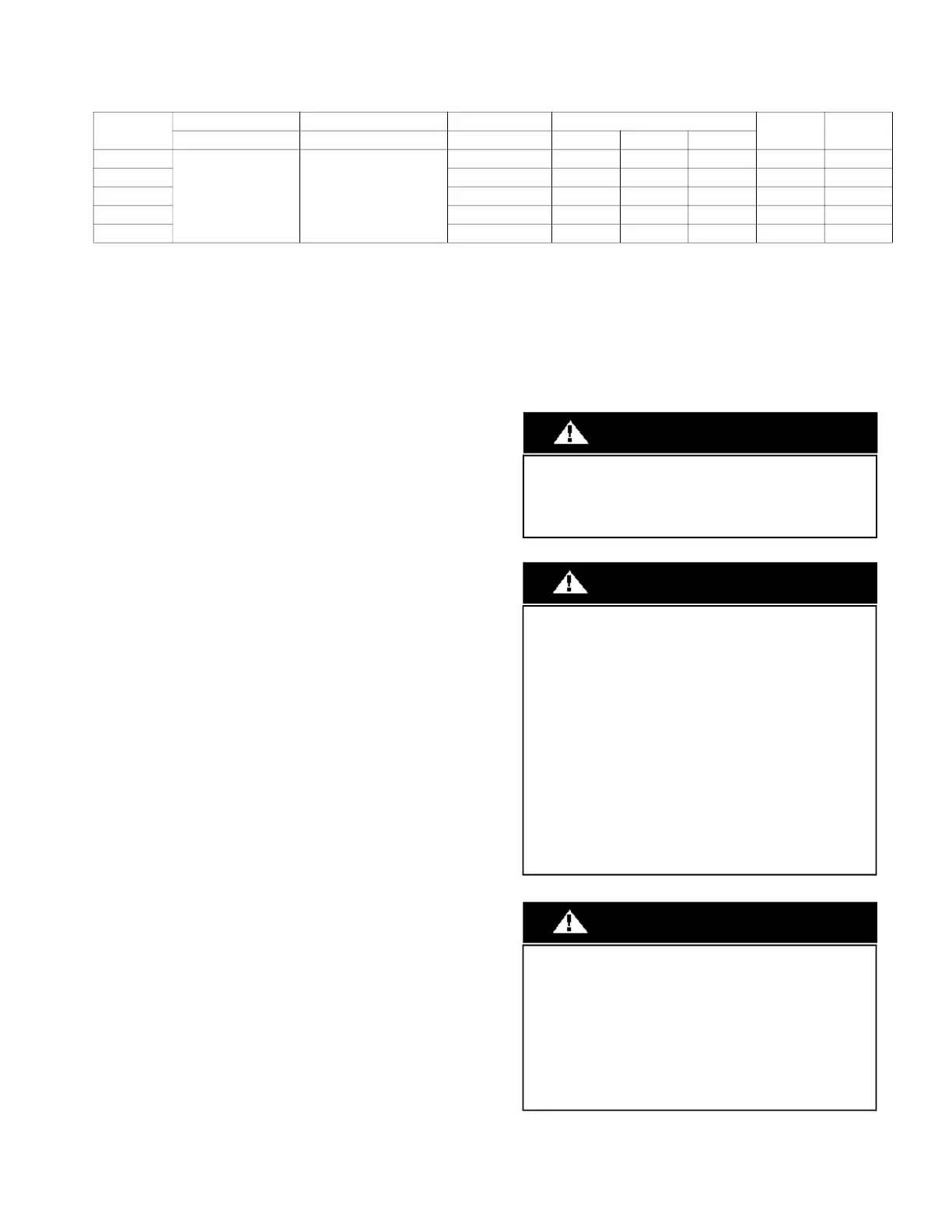
Table 5 — Electrical Data
*Permissible limits of the voltage range at which the unit will operate satisfactorily.
LEGEND
• FLA - Full Load Amps
• MCA - Minimum Circuit Amps
• MOCP - Maximum Over Current Protection
• RLA - Rated Load Amps
WIRING
All wires must be sized per NEC (National Electrical Code) or CEC
(Canadian Electrical Code) and local codes. See the rating plate and/
or the installation instructions of the compatible outdoor unit for MCA
(minimum circuit amps) and MOCP (maximum over current
protection) to correctly size the wires and the disconnect fuse or
breakers respectively.
Recommended Connection Method for Power and
Communication Wiring:
The main power is supplied to the outdoor unit. The field supplied 14/
3 stranded wire with ground with a 600 volt insulation rating, power/
communication wiring from the outdoor unit to indoor unit consists of
four (4) wires and provides the power for the indoor unit. Two wires
are line voltage AC power, one is communication wiring (S) and the
other is a ground wire. Wiring between indoor and outdoor unit is
polarity sensitive. The use of BX wire is NOT recommended.
If installed in a high Electromagnetic field (EMF) area and
communication issues exists, a 14/2 stranded shielded wire can be
used to replace L2 and (S) between outdoor unit and indoor unit
landing the shield onto ground in the outdoor unit only.
UNIT SIZE
SYSTEM VOLTAGE OPERATING VOLTAGE COMPRESSOR OUTDOOR FAN
MCA MOCP
VOLT / PHASE / HZ MAX / MIN* RLA FLA HP W
18
208-230/1/60 253 / 187
10 0.74 0.07 50 18 25
24 15 0.9 0.16 120 25 35
30 19 1.3 0.16 120 30 45
36 21 1.0x2 0.11 85 35 50
48 21 1.0x2 0.11 85 35 50
EQUIPMENT DAMAGE HAZARD
Failure to follow this caution may result in equipment damage
or improper operation.
Wires should be sized based on NEC and local codes.
CAUTION
EQUIPMENT DAMAGE HAZARD
Failure to follow this caution may result in equipment damage
or improper operation.
Be sure to comply with local codes while running wire from
the indoor unit to the outdoor unit.
Every wire must be connected firmly. Loose wiring may
cause the terminal to overheat or result in unit malfunction. A
fire hazard may also exist. Ensure all wiring is tightly
connected.
No wire should touch the refrigerant tubing, compressor or
any moving parts.
Disconnecting means must be provided and shall be located
within sight and readily accessible from the air conditioner.
Connecting cable with conduit shall be routed through the
hole in the conduit panel.
CAUTION
AUTO mode is recommended to be used on single zone
applications ONLY, it is NOT recommended to be used on
multi-zone Applications.
Using AUTO changeover on multi-zone applications could
set an indoor unit on STANDBY, indicated as (--) on the
display, turning off this indoor unit until all the indoor units
are on the same mode (COOLING or HEATING).
HEATING mode is the priority in the system.
Simultaneous HEATING and COOLING is not allowed.
WARNING
 Loading...