– 11 –
4
Wired remote controller
This remote controller can control the operation of up to 8 indoor units.
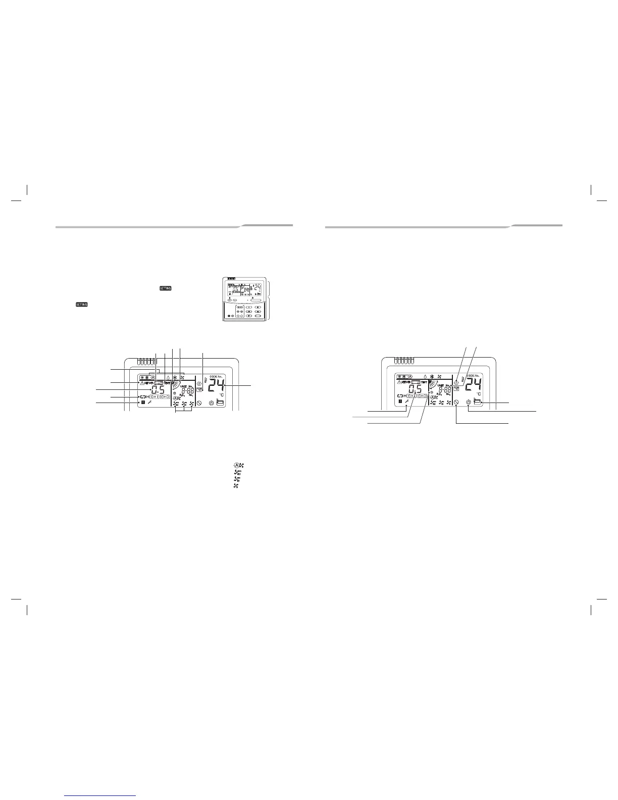
4-1. Display section
In the display illustration below all the icons are shown. When the unit is in operation,
only relevant icons will be displayed.
• When the leak breaker is turned on for the first time, flashes on the display
part of the remote controller.
• While this icon is flashing, the model is being automatically confirmed.
Wait till icon has disappeared to use the remote controller.
1 Operation mode
The selected operation mode is displayed.
2 Error display
Displayed while the protective device works or a error
occurs.
3 SETTING display
Displayed during setup of the timer or other settings.
4 TEST run display
Displayed during a test run.
5 Timer display
When an error occurs, error code is displayed.
6 Timer mode display
The selected timer mode is displayed.
7 Louver position display
Displays louver position.
8 Swing display
Displayed during up / down movement of the louver.
9
Filter display
Reminder to clean the air filter.
10
Fan speed display
The selected fan speed mode is displayed.
11
Set temperature display
The selected set temperature is displayed.
12
Power saving mode display
Limits compressor speed (capacity) to save energy.
SET
TIME
TIMER SET
TEST
FILTER
RESET
TEMP.
CL
FAN
SAVE
SWING/FIX
VENT
MODE
ON / OFF
UNIT LOUVER
Display
section
Operation
section
1
6
2
5
9
10
4
12
3
11
87
(Auto)
(High)
(Med.)
(Low)
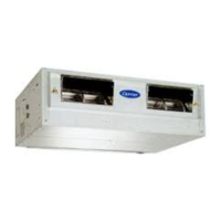
13
UNIT No. display
Displays the number of the indoor unit selected.
Also displays error code of indoor and outdoor units.
14
Remote controller sensor display
Displayed while the sensor of the remote controller is
used.
15
No function display
Displayed when the function requested is not available
on that model.
16
Self clean operation display
Displayed during self clean operation to dry the indoor
heat exchanger.
17
Service display
18
Operation ready display
This display appears on some models.
19
Louver Number display.
(exapmle:01, 02, 03, 04)
20
Louver lock display
Displayed when there is a louver-locked unit in the
group (including 1 indoor unit by 1 outdoor unit).
14
15
13
18
16
17
19
20
22-EN21-EN