58
(SEE NOTE 5)
(SEE NOTE 4)
UNIT
BOTTOM
LEFT SIDE
VIEW
(SEE NOTE 5)
2
3
4
5
6
7
8
9
10
11
12
13
14
1
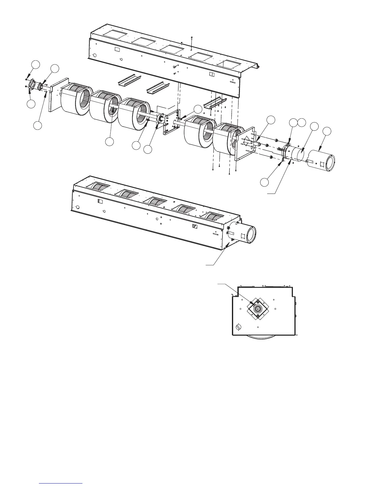
Fig. 40 — 40UH200 Ventilator Blower Drive Train Assembly
NOTES:
1. Not all components shown for clarity.
2. This drawing applies to 2000 cfm units only.
3. Remove shaft, motor and coupling prior to removing bearing.
Refer to Ball Bearing Replacement instructions.
4. Install sleeve bearing with oil cup facing up and towards the rear of
the assembly.
5. Refer to Fig. 36 for motor-coupling and shaft-coupling tolerances.
 Loading...


