108
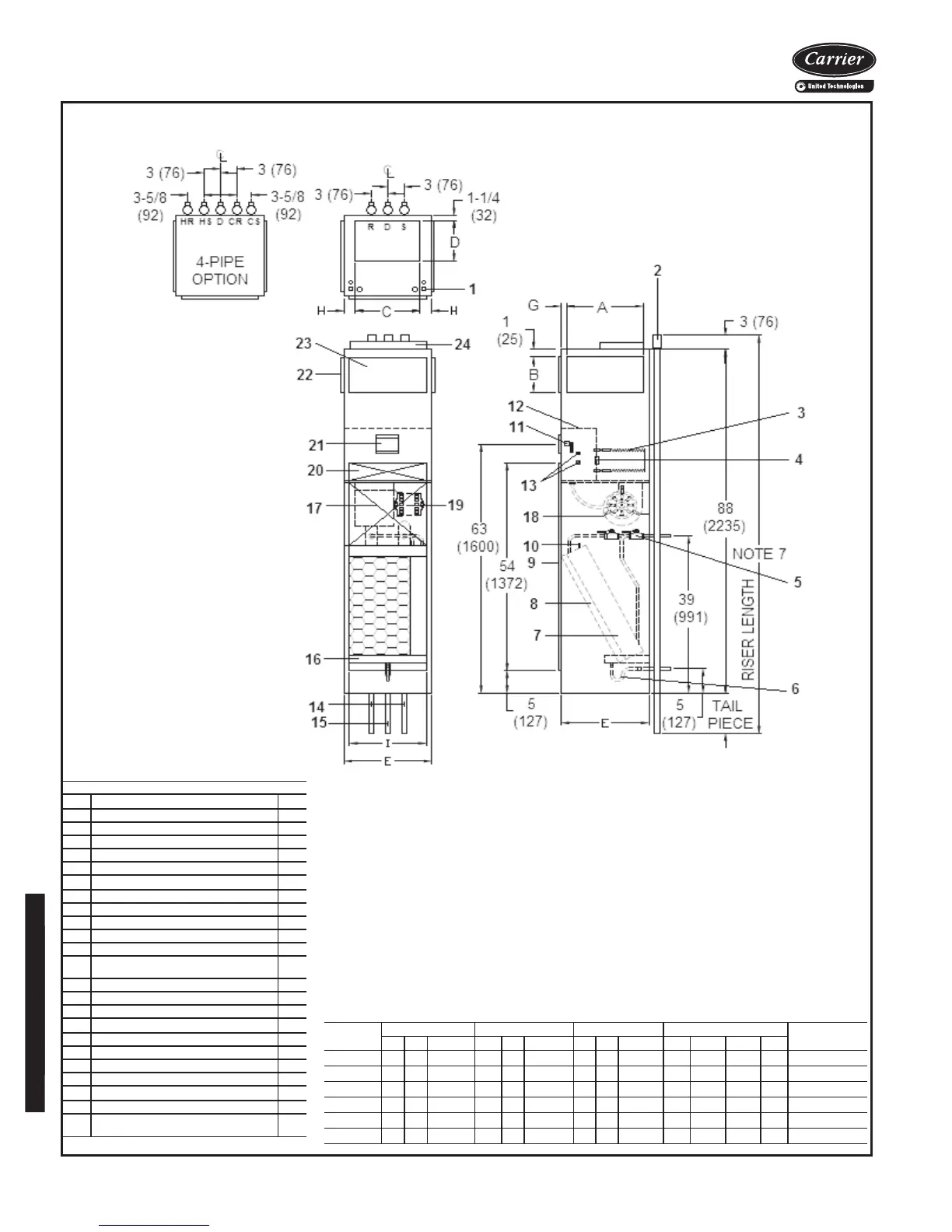
NOTES:
1. Units are fabricated of galvanized steel with a 16-gage galvanized fan deck.
2. All risers are insulated with (
1
/
2
-in. or
3
/
4
-in. thick) closed cell insulation.
3. Thermostat shipped loose for field installation when ordered with the unit.
4. Risers are piped to coil with valve package as specified.
5. Blower, motor, coil, valves, and filter are accessible through the return air opening.
6. Unit and control box are insulated.
7. Riser length = [(floor to floor) +2 in.], maximum riser length = 119 inches.
8. Maximum riser size is 2
1
/
2
-in. diameter. If larger size is required, please consult the factory.
9. Expansion loops in hot water heating circuits as required.
10. Drawing is pictorial (see unit arrangements for actual supply and return air orientation).
11. Dimensions are in inches. Dimensions in () are in millimeters.
12. A 9-in. x 2
1
/
4
-in. slot is provided in the inside back panel for coil connection penetration to permit
expansion and contraction of riser. Care must be taken to position the riser so that coil connection is at
center of slot.
42SGM FURRED-IN STACK MASTER UNIT
UNIT
MODEL
SINGLE SUPPLY DOUBLE SUPPLY TOP SUPPLY DIMENSIONS - INCHES
FILTER SIZE
A B SIZE A B SIZE C D SIZE E G H I
42SGM03 14 8 14 X 8 14 6 14 X 6 14 10 14 x 10 17 1
1
/
2²
1
1
/
2²
14 12
1
/
2
X 24
¹
/
4
X 1
42SGM04 14 12 14 X12 14 6 14 X 6 14 10 14 x 10 17 1
1
/
2²
1
1
/
2
14 12
1
/
2
X 24
¹
/
4
X 1
42SGM06 18 10 18 X10 18 6 18 X 6 16 12 16 x 12 20 1 2 18 16
¹
/
4
X 26
3
/
4
X 1
42SGM08 18 12 18 X 12 18 6 18 X 6 16 12 16 x 12 20 1 2 18 16
¹
/
4
X 26
3
/
4
X 1
42SGM10 — — — 22 8 22 X 8 18 16 18 x 16 24 1 3 22 20
1
/
2
X 29
¹
/
4
X 1
42SGM12 — — — 22 8 22 X 8 18 16 18 x 16 24 1 3 22 20
1
/
2
X 29
¹
/
4
X 1
ITEM DESCRIPTION QTY
1 Electrical Knockouts
1
2 3-in. Expanded Section of Riser 3/5
3 Strip Heater (Optional) 1
4 Limit Switch (Optional) 1
5
1
/
2
-in. Isolation Ball Valve 2/4
6 Flexible Drain Tube/P-Trap 1
7 Coil
1
/
2
-in. OD Copper Tube
1
8 Filter, Throwaway, 1-in. 1
9 Return Air Opening 1
10 Air Vent, Manual 1
11 Molex Connector for Field-Installed Tstat 1
12 Control Box 1
13
Knockout (For Optional Remote Mounting)/
Side
2
14 Riser, Supply and Return (Copper) 2/4
15 Riser, Drain (Copper) 1
16 Drain Pan 1
17
Acoustical Bypass Panel 1
18 Blower 1
19 Motor, 3-Speed, PSC, with Quick Connect 1
20 Access Panel (Control Box) 1
21 Control Opening (Surface Mount Tstat) 1
22 Duct Collar,
1
/
2
-in. Extension (Typical)
1/2/3
23 Supply Air Opening(s) 1/2/3
24
Top Supply Duct Collar, 1-in. Extension
(Optional)
1
A42-4127
LEGEND
CR — Cold Water Return
CS — Cold Water Supply
D —Drain
HR — Hot Water Return
HS — Hot Water Supply
R — Return
S — Supply
Base unit dimensions (cont)

 Loading...


