39
1
2
3
1
(25)
3
(76)
B
A
2-1/4
(64)
1-1/8
(29)
6
(152)
1-1/2
(38)
D’
A’
5
4
E
MTG. HOLES
H
6
3/4
(19)
3/4
(19)
11
5
16
(406)
SUPPLY
AIR
F
G
7/8
(22)
7
10
8
9
17-1/2
(445)
8-3/8
(213)
1
(25)
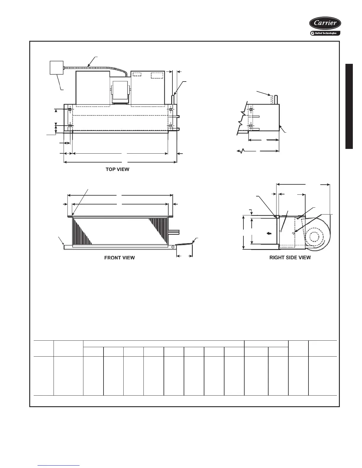
42CA FURRED-IN HORIZONTAL UNIT
LEGEND
1—Junction Box (remote mount)
2—Flexible Metal Conduit
3—Drain Conn,
7
/
8
-in. OD
4 — Tell-Tale Drain Conn,
5
/
8
-in. OD (optional)
5—Drip Lip (optional)
6—Hanger Slots (4), Rubber Grommet
has
3
/
8
-in. Diameter Hole
7—Supply Duct Collar, 1-in.
8—Air Vent,
1
/
8
-in. MPT
9—Return Conn,
5
/
8
-in. OD
10 — Supply Conn,
5
/
8
-in. OD
11 — Drain Pan
*Unit weights are based on dry coils and minimum rows. Weights exclude packaging, valves, and other components.
UNIT
SIZE
NOM
AIRFLOW
(Cfm)
DIMENSIONS (in.) QTY/UNIT FACE
AREA
(sq ft)
UNIT
WEIGHT*
(lb)
AA’BD’E F G H
Blower Motor
02 200 21
1
/
4
31
1
/
4
16 13 18
1
/
4
6
1
/
4
8
3
/
4
19
3
/
4
1 1 0.83 36
03 300 25
1
/
4
36
1
/
4
20 14 22
1
/
4
6
1
/
4
8
3
/
4
23
3
/
4
1 1 1.08 39
04 400 31
1
/
4
43
1
/
4
26 15 28
1
/
4
6
1
/
4
8
3
/
4
29
3
/
4
2 1 1.35 49
06 600 36
1
/
4
43
1
/
4
31 10 33
1
/
4
7
1
/
2
10 34
3
/
4
2 1 1.88 59
08 800 43
1
/
4
57
1
/
4
38 17 40
1
/
4
7
1
/
2
10 41
3
/
4
2 1 2.31 64
10 1000 57
1
/
4
65
1
/
4
52 11 54
1
/
4
7
1
/
2
10 55
3
/
4
4 2 3.16 95
12 1200 65
1
/
4
75
1
/
4
60 13 62
1
/
4
7
1
/
2
10 63
3
/
4
4 2 3.65 107
NOTES:
1. Right hand unit shown; left hand unit opposite. Coil connection loca-
tions are ±
5
/
8
-inches.
2. Unit sizes 02 and 03 have one motor, one blower; sizes 04 through
08 have one motor, 2 blowers; sizes 10 and 12 have 2 motors,
4 blowers.
3. Standard 3-row coil shown.
4. Overall unit dimension increases by 4 in. with optional electric heat.
5. Not shown: 3-speed fan switch; wall plate, closed cell foam on main
drain pan.
6. Units have galvanized finish.
7. See 42CA-203-1 for optional coil connections.
8. Dimensions shown in inches (mm).
a42-4099.eps
Base unit dimensions

 Loading...


