28
Valve packages
There are limitations on physical size of pneumatic valves,
quantity and type of matching components, and required
control interface. See Symbols and Placement of Valves
diagram.
Consult factory before ordering any special valve pack-
age components that are not covered in this book.
Valve packages are shipped with the units or in unit car-
tons. Valve packages include belled ends for field soldering
to coil connections.
All factory-furnished cooling valve packages are
arranged to position as much of the package as possible
over an auxiliary drain pan or drip lip. This helps minimize
field piping insulation requirements.
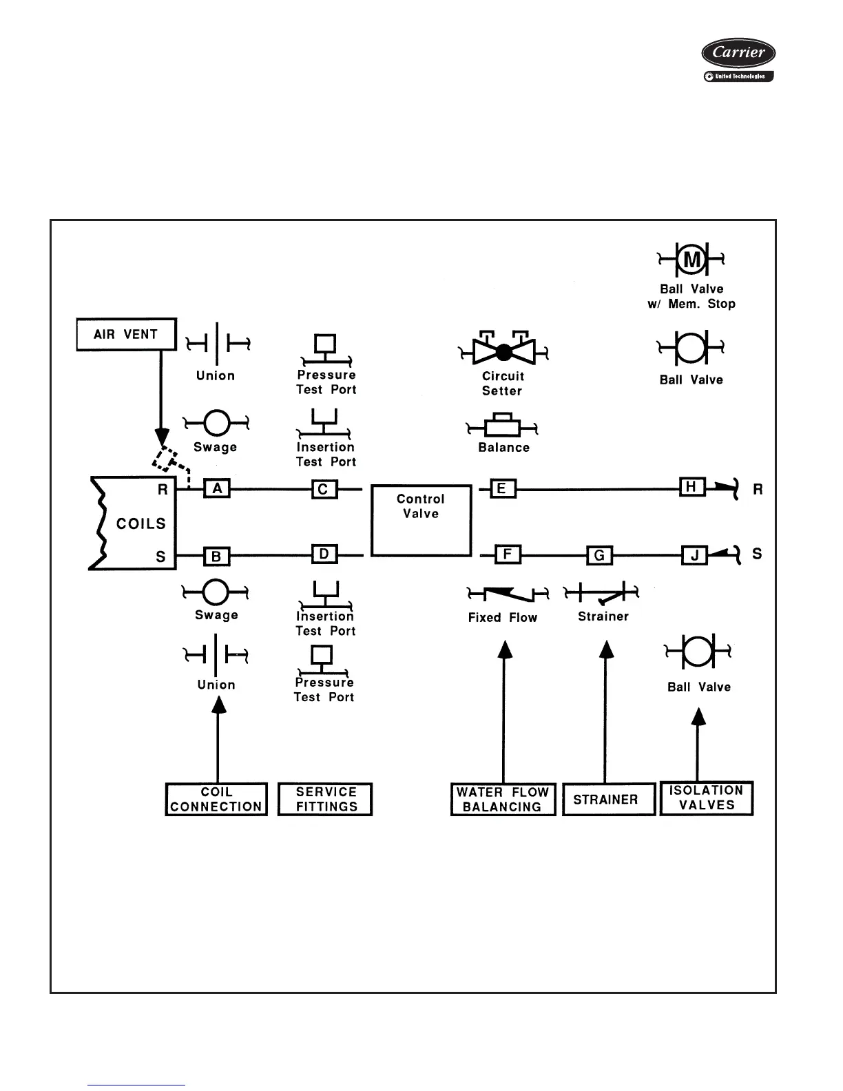
SYMBOLS AND PLACEMENT OF VALVES
Coil Connections (Positions A & B) — When isolation valve only is added to supply or return line, the isolation valve will be factory
brazed to the coil stub-out. Addition of any other component or connection to the supply or return line will change the respective coil
connection(s).
Service Fittings (Positions C & D) — Optional fittings for attaching pressure/temperature sensing devices to obtain pressure drop or tem-
perature differential across coil. Used with ball valve or balance valve where extremely accurate water flow balancing is required.
Water Flow Balancing (Positions E, F, & H) — Only one device per total valve package to be used for balancing water flow through the
coil. When isolation valve (ball valve or ball valve with memory stop at position H) is used for water flow balancing, do not specify additional
balancing device at position E or F. When balancing device is specified at position E or F, isolation valve does not require balancing feature
at position H (with a 3-way motorized valve, a bypass balancing valve may be specified in the bypass line to permit equal flow balancing).
Strainer (Position G) — Does not include blow down fitting and should not be used in lieu of main piping strainers.
Isolation Valves (Positions H & J) — Normally requires one each on supply and return line (see exception under circuit setter). When
position H is used for balancing (ball valve or ball valve with memory stop), check specifications for service valve requirements.
a42-4222
Application data (cont)

 Loading...


