27
PIPING COMPONENTS (cont)
LEGEND *Check all system component pressure ratings (coils, values, pumps,
etc.) with manufacturer and any applicable local or national piping
codes prior to specifying system pressure rating.
SYMBOL/SKETCH DESCRIPTION
C
V
FACTOR RATING*
STEAM
USE
1
/
2
3
/
4
PSI F
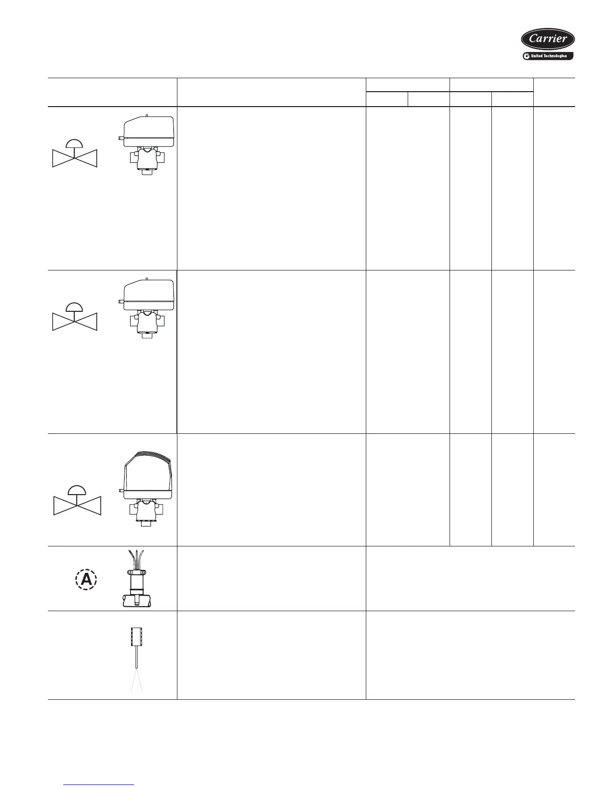
MODULATING VALVE (Optional)
(Non-Spring Return, Floating Point Actua-
tor): Modulating valves are designed to con-
trol the flow in the circuit by making
incremental adjustments to the flow path
within the valve.
Application — To control fluid flow in fan coil
units.
On the 42DD,SG,SJ,SH commercial fan coil
models, the factory provided modulating valve
has application restrictions. In these models,
the valve packages are located in the air-
stream, downstream of the coil. Due to the
ambient temperature limitations of the modu-
lating valves, the valves can only be used in
the units listed above with 2-pipe cooling only
systems.
4.0 300 200 N/A
MODULATING VALVE (Optional)
(Non-Spring Return, Proportional Type
Actuator): Modulating valves are designed to
control the flow in the circuit by making incre-
mental adjustments to the flow path within the
valve.
Application — To control fluid flow in fan coil
units.
On the 42DD,SG,SJ,SH commercial fan coil
models, the factory provided modulating valve
has application restrictions. In these models,
the valve packages are located in the air-
stream, downstream of the coil. Due to the
ambient temperature limitations of the modu-
lating valves, the valves can only be used in
the units listed above with 2-pipe cooling only
systems.
4.0 300 200 N/A
MODULATING VALVE (Requires ETO)
(Spring Return): Modulating valves are
designed to control the flow in the circuit by
making incremental adjustments to the flow
path within the valve.
Application — Same comments as non-spring
return except when powered, the actuator
moves to the desired position, at the same
time tensing the spring return system. When
power is removed for more than two minutes
the spring returns the actuator to the normal
position.
4.0
300 200
N/A
AQUASTAT: Water temperature sensing elec-
trical switch. (Line Voltage Controls)
Application — Clips directly on nominal
size
1
/
2
in. or
3
/
4
in. copper tubing for water
temperature sensing. Must be correctly
located for proper control operation.
CHANGEOVER SENSOR: Water tempera-
ture sensor thermistor.
Application — Sensor shall clamp on the out-
side diameter of the pipe. Sensor plate shall
bend to allow its radius to be adjusted to fit the
pipe. Sensor shall be secured to the pipe with
mounting clamp. Insulate the mounting loca-
tion of sensor on the pipe.
Cv — Coefficient of Velocity
DX — Direct Expansion
ETO — Engineering to Order

 Loading...


