20
Risers (42S units)
Riser diameter is an important consideration in the design
of stack series systems. Standard units can accommodate
3
/
4
-in. to 2
1
/
2
-in. riser sizes in 2-pipe systems. For other
applications, such as reverse return risers or 4-pipe sys-
tems, it may be necessary to accommodate the additional
risers.
Riser size is based on the water flow needed for a given
tier of units. Unit risers are sized according to the diameter
and length requirements as specified by the customer. To
determine riser size, water velocity should be limited to 5 to
8 ft per second. Thus, if 10 units are to be stacked verti-
cally with each unit requiring 3 gpm, the maximum flow in
the risers is 30 gpm. Through 1
1
/
4
in. risers, this is a veloc-
ity of 7.5 ft per second. The maximum flow rate of
30 gpm occurs only at the supply and return points. As the
water moves upward, the flow in the supply riser is reduced
by 3 gpm per floor, so that after 3 floors, the total flow is
21 gpm and riser size can be reduced to one inch. See the
Main Riser Pressure Drops chart on page 125.
Condensate drains are available in sizes down to 1 in. for
greater first cost economy.
Riser size-reducers are factory installed and caps are pro-
vided at customer request except for 42SU units.
For risers of over 119 in. length, extension pieces can
be furnished for field installation.
Typical arrangements
Typical arrangement applications for each model type are
shown on page 21. The fan coil units feature almost an
unlimited number of arrangements to meet the needs of
new construction, renovation, or reconstruction. Consult
the factory for the arrangement (standard or special) to
meet your particular need.
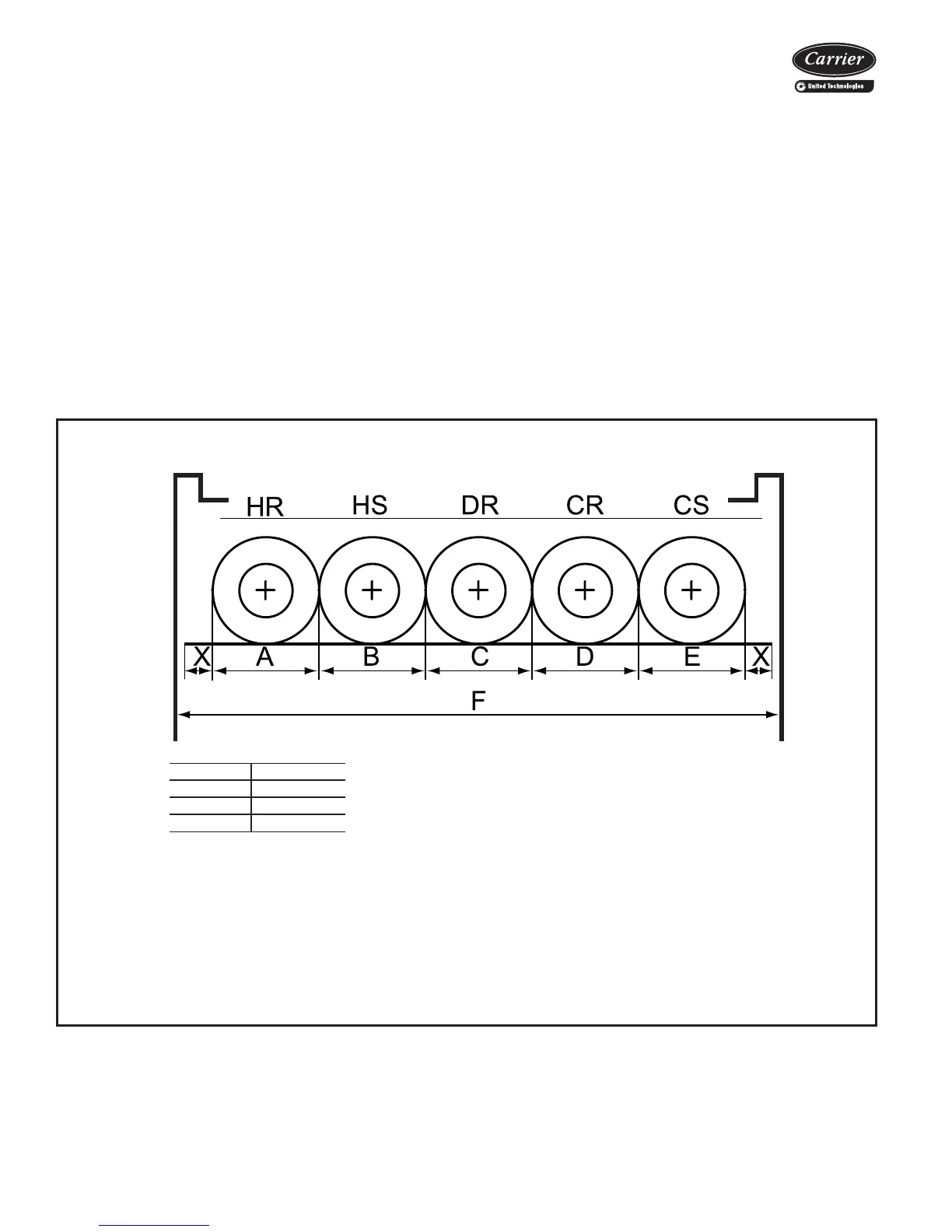
MAXIMUM RISER DIAMETER DIAGRAM
LEGEND
NOTES:
1. The F dimension is determined by the following formula: X + A + B + C + D + E + X = F
(where X =
7
/
16
in.)
2. The largest diameter riser in each tier must be able to fit in the smallest size cabinet and
not exceed the F dimension.
3. For unit sizes 14-20, contact application engineering.
UNIT SIZE F DIMENSION
03,04 17 in.
06,08 20 in.
10,12 24 in.
CR — Cold Water Return
CS — Cold Water Supply
DR — Drain
HR — Hot Water Return
HS — Hot Water Supply
a42-3986
Application data (cont)

 Loading...


