95
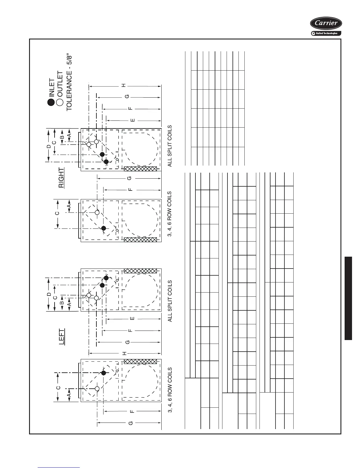
42DD OPTIONAL COIL CONNECTION LOCATION SIZES 06–20
a42-3997
NOTES:
1. Does not apply to connection size when optional valve packages are used.
2. Cooling coil is first in the airstream.
3. Split coil connections shown are for 4-pipe combination chilled water/hot water coils only,
with hot water in the reheat position, as standard.
UNIT CFM
COIL CONNECTION DIMENSIONS (in.)
3-Row 4-Row 6-Row
ACFGACFGACFG
Right
Hand
600-800
1000-2000
6
11
/
16
5
3
/
8
8
1
/
2
9
7
/
8
26
23
15
/
16
24
7
/
8
27
4
1
/
2
10
3
/
16
23
3
/
8
26
1
/
2
3
1
/
2
11
1
/
8
23
15
/
16
25
7
/
8
Left Hand
600-800
1000-2000
7
5
3
/
8
8
7
/
8
10
3
/
16
7
15
/
16
5
7
/
16
24
3
/
8
26
1
/
2
4
3
/
4
9
7
/
8
23
15
/
16
25
15
/
16
3
7
/
8
10
3
/
4
24
1
/
2
25
3
/
8
UNIT CFM
COIL CONNECTION DIMENSIONS (in.)
3 and 1 Split Coil 3 and 2 Split Coil
ABCDEFGHABCDEFGH
Right
Hand
600-800
1000-2000
5
3
/
4
4
7
/
16
5
1
/
4
5
1
/
4
7
5
/
8
8
15
/
16
12
7
/
16
12
7
/
16
19
11
/
16
19
11
/
16
25
7
/
16
23
5
/
16
24
5
/
16
26
7
/
16
31
5
/
16
31
5
/
16
5
3
/
4
4
7
/
16
5
9
/
16
5
9
/
16
7
5
/
8
8
15
/
16
12
3
/
4
12
3
/
4
20
1
/
4
20
1
/
4
25
7
/
16
23
5
/
16
24
5
/
16
26
1
/
16
31
7
/
8
31
7
/
8
Left
Hand
600-800
1000-2000
6
1
/
8
4
3
/
4
4
15
/
16
4
15
/
16
7
15
/
16
9
1
/
4
12
1
/
8
12
1
/
8
20
3
/
16
20
3
/
16
24
15
/
16
22
13
/
16
23
3
/
4
25
15
/
16
31
7
/
16
31
7
/
16
6
1
/
8
4
3
/
4
5
9
/
16
5
9
/
16
7
15
/
16
9
1
/
4
12
3
/
4
12
3
/
4
20
1
/
4
20
1
/
4
24
15
/
16
22
13
/
16
23
3
/
4
25
7
/
8
31
7
/
8
31
7
/
8
UNIT CFM
COIL CONNECTION DIMENSIONS (in.)
4 and 1 Split Coil 4 and 2 Split Coil
ABCDE FGHABCDE FGH
Right
Hand
600-2000 4
7
/
16
5
13
/
16
10
3
/
16
13
1
/
16
20
3
/
4
23
3
/
8
26
7
/
16
32
7
/
16
3
1
/
2
5
9
/
16
9
1
/
4
12
3
/
4
20
1
/
4
22
13
/
16
25
7
/
8
31
7
/
8
Left
Hand
600-2000 4
3
/
4
6
13
/
16
9
7
/
8
13
3
/
8
20
1
/
4
23
7
/
8
25
7
/
8
31
7
/
8
3
7
/
8
5
9
/
16
8
15
/
16
12
3
/
4
20
1
/
4
23
5
/
16
25
3
/
8
31
7
/
8
NOTE: Does not apply to connection size when
optional valve packages are used.
COIL CONNECTIONS SIZES (OD COPPER SWEAT) (in.)
cfm 1-2 Row 3 Row 4 Row 5 Row 6 Row
600
5
/
8
5
/
8
7
/
8
7
/
8
7
/
8
800
5
/
8
5
/
8
7
/
8
7
/
8
7
/
8
1000
5
/
8
7
/
8
7
/
8
7
/
8
7
/
8
1200
5
/
8
7
/
8
7
/
8
7
/
8
7
/
8
1400
5
/
8
7
/
8
7
/
8
1
1
/
8
1
1
/
8
1600
5
/
8
7
/
8
1
1
/
8
1
1
/
8
1
1
/
8
1800
5
/
8
7
/
8
1
1
/
8
1
1
/
8
1
1
/
8
2000
5
/
8
7
/
8
1
1
/
8
1
1
/
8
1
1
/
8

 Loading...


