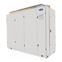
10 - CONNECTIONS
Electrical specications:
Three-phase 400 V power supply + Earth - 50 Hz
Table of currents
W 40 W 53 W 78 W 100 W 115
Fan motor assembly
Voltage (V) 400
Power (kW) 3,4 6,8 9,3
Current (A) 5,4 10,8 14,7
Control circuit (transformer)
Voltage (V) 24
Current (A) 1
Humidier (option)
Voltage (V) 400
Power (kW) 6
Current (A) 8,7
Electric heater (option)
Voltage (V) 400
Power (kW) 12 18 24 33,6 33,6
Current (A) 17,4 26 34,6 48,4 48,4
Total current without option
Current (A) 6,4 6,4 11,8 11,8 15,7
Rating of main switch (A) 16 25
Total current with humidier
Current (A) 15,1 15,1 20,5 20,5 24,4
Rating of disconnect switch (A
) 25 40
Total current with electric heater
Current (A) 23,8 32,4 46,4 60,2 64,1
Rating of main switch (A) 40 63 80
Total current all options
Current (A) 32,5 41,1 55,1 68,9 72,8
Rating of main switch (A) 40 63 80
Recommendations concerning electrical connections of the indoor unit.
Connect the indoor unit so that the main power supply comes from underneath the unit.
Either on the right side of the unit (1 or 2) or from underneath (3). If using a cased base, pass it through one of the grommets on the
right side intended for this purpose (See technical specications).
D
C
B
10
 Loading...