11 - TECHNICAL SPECIFICATIONS
Filter fouling is measured by a pressure sensor located in the electrics box.
It is set to 1.5 times the value for the lter when clean (pressure ports upstream and downstream of the lter).
11.1.5 - Standard control elements:
(Factory cables)
- An intake temperature sensor.
- A dierential pressure sensor: attached to the electrics box, this allows the dierence in pressure upstream and downstream of
the lter to be measured, so as to determine whether the lter is fouled.
- A water leak sensor: this is found at the end of a wound cable located at the bottom of the unit so that it is long enough to extend
downwards into a raised oor, if required, and to be positioned in the area to be monitored. It can be added on request.
It can be added on request.
11.2 - Optional Components
11.2.1 - Heating coil
Moderately tighten the "coil supply" connections to avoid damaging the manifolds.
The coil is adjusted by a two-way or four-way valve equipped with a 0-10V servomotor (mounted and connected).
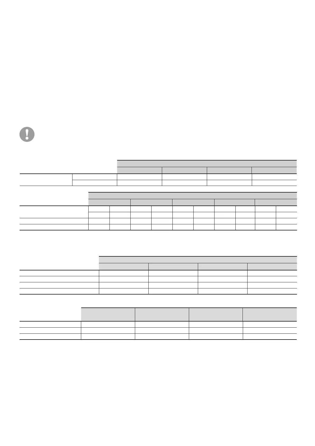
Coil specications:
HOT WATER
W40 W53 W78 W100
Coil (1 row)
Number of coils 1 1 1 1
Capacity (l) 3,82 4,92 6,29 6,29
HEATING COIL
W40 W53 W78 W100 W115
Air ow (m3/h)
Nominal Maximum Nominal Maximum Nominal Maximum Nominal Maximum Nominal Maximum
10 000 13 300 13 300 13 300 18 800 20 500 24 500 27 000 27 000 27 500
Heating capacity (kW)* 36 40 44 44 63 66 71 73 - -
Heating capacity (kW)** 18 21 23 23 33 34 37 38 - -
* Conditions: return air 17 °C - 50 %, water temperature 80/60 °C
** Conditions: return air 17 °C - 50 %, water temperature 45/40 °C
Heating coil pressure drop*:
HOT WATER
W40 W53 W78 W100
Nominal water ow (m³/h) 0,9 1,1 1,68 1,9
KV valve 4 4 4 4
∆P Valve only (mWC) 0,6 0,8 1,8 2,3
∆P (Pa) Valve + Coil (mWC) 1,5 1,8 3 3,8
Nominal ow rate: water ∆T: 20 °C
W40 W53 W78 W100
KV 4 4 4 4
∆P max.¹ Four-way valve 240 240 240 240
∆P max.² Two-way valve 400 400 400 400
15
 Loading...