59MN7C: Installation, Start-up, Operating and Service and Maintenance Instructions
Manufacturer reserves the right to change, at any time, specifications and designs without notice and without obligations.
20
The following equations relate Face Velocity (FPM), Filter Area and Airflow (CFM):
Filter Face Velocity = Airflow / Filter Area
Minimum Filter Area = Rated System Airflow / Maximum Filter Face Velocity
Optional Filter Media Pressure Drop (Clean) Versus Face Velocity- in. w.c. (Pa)
Air Filter Located in Filter Cabinet
A11437
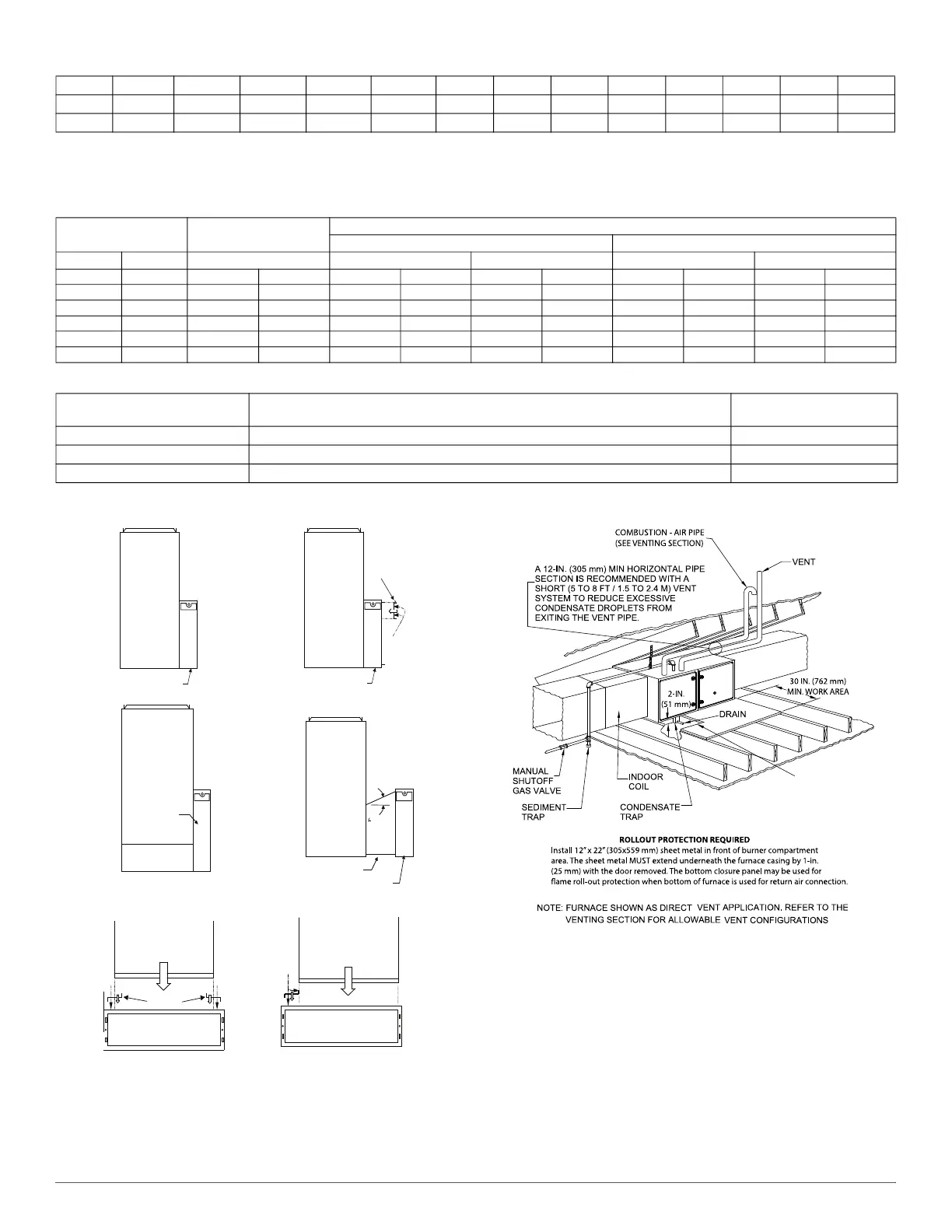
Fig. 26 – Optional Media Filter
A150580
NOTE: Local codes may require a drain pan and condensate trap when a
condensing furnace is installed over a finished ceiling.
Fig. 27 – Working Platform for Attic Installation
1800 (850) 0.07 (18) 0.14 (35) 0.13 (34) 0.21 (53) - - - -
2000 (944) 0.08 (19) 0.16 (41) 0.16 (39) 0.24 (61) - - - -
2200 (1038) 0.08 (21) 0.19 (49) 0.18 (45) 0.28 (70) - - - -
Face Velocity
Factory-Accessory
Washable
Representative After-Market Filter Media*
Fiberglass* Pleated*
FPM (m/s) (1-in. / 2.5 cm) (1-in. / 2.5 cm) (2-in. / 5 cm) (1-in. / 2.5 cm) (2-in. / 5 cm)
200 (1) 0.04 (10) 0.05 (13) 0.08 (20) 0.18 (47) 0.12 (31)
300 (1.5) 0.05 (14) 0.09 (22) 0.13 (34) 0.30 (75) 0.21 (52)
400 (2) 0.07 (17) 0.13 (32) 0.20 (50) - - 0.31 (78)
500 (2.5) 0.08 (21) 0.18 (44) 0.27 (69) - - - -
600 (3) 0.09 (23) 0.23 - - - - - - -
700 (3.6) 0.10 (26) 0.29 - - - - - - -
FILTER CABINET HEIGHT - IN
(MM)
FILTER SIZE - IN (MM) FILTER TYPE
16 (406) (1) 16 x 25 x 3/4* (406 x 635 x 19) or (1) 16 x 25 x 4-5/16 (406 x 635 x 110)
Washable or Media
*
*. Filters with a side return-air may have a different filter size. Measure the filter to obtain the correct size.Recommended to maintain air filter face velocity. See Product Data for
part number.
20 (508) (1) 20 x 25 x 3/4* (508 x 635 x 19) or (1) 20 x 25 x 4-5/16 (508 x 635 x 110)
Washable or Media
*
24 (610) (1) 24 x 25 x 3/4*or (610 x 635 x 19) or (1) 24 x 25 x 4-5/16 (610 x 635 x 110)
Washable or Media
*
Optional Filter Media Pressure Drop (Clean) Versus Airflow - in. w.c. (Pa) (Continued)
14-3/16 and 17-1/2-in.
Furnace
16-in. Media Cabinet
21-in. Furnace
4-Ton or less, AC
capacity airflow
20-in. Media Cabinet
4-in.
Block Off
Plate
1/2-in.
Screws
20- or 24-in. Media
Cabinet
Bottom Return Plenum
21- or 24-1/2-in.
Furnace
Up to 5-Ton AC
capacity airflow
45°
Transition
20- or 24-in. Media Cabinet
Screw
14-3/16-in. Furnace
Filler plates
Screw
14--3/16-in. Furnace with Filler Plates, Centered
14-3/16-in. Furnace
Filler plate
Screws
14--3/16-in. Furnace with Filler Plates, Off--Set to Right
Media Cabinet Installation Option for
4-Ton or Less A/C Capacity
20- or -24-in. Media Cabinet Installation
with Angled Transition
20- or -24-in. Media Cabinet Installation
for Combination Side and Bottom Return
Media Cabinet Installation
Side Return
21-in. Furnace
up to 5-Ton AC
Capacity
24-1/2-in. Furnace
up to 4-Ton AC
Capacity


 To Next Page