59MN7C: Installation, Start-up, Operating and Service and Maintenance Instructions
Manufacturer reserves the right to change, at any time, specifications and designs without notice and without obligations.
46
For Heating Settings
Eff1 airflow will give midpoint rise
Eff2 will increase heating airflow (when unit is capable)
Com2 will decrease heating airflow (default)
Com1 will give the lower heating airflow
Notes:
ESP is External Static Pressure
Airflow values up to 1 in. w.c. ESP (unless noted)
FURNACE CONTROL PROGRAMMING
AND NAVIGATION
On-Board Control Method
This furnace model is equipped with an on-board 3-digit LCD display
with pushbutton navigation for the adjustment of operating parameters,
diagnostics, and service. The control board must be powered to use the
display and pushbuttons. Upon startup, the control will alternate display
the Model Program Number (PRG) and Software Version (uEr). The
control board has been programmed at the factory with a Model Program
Number specific to the furnace product number. The correct Model
Program Number is shown on the furnace rating plate.
The system’s status is displayed after startup or after no control buttons
have been pressed for 60 seconds. Status Code LED will also be
illuminated or blinking when displaying the system status. The codes
which indicate the current operating mode of the system as shown in
Table 17.
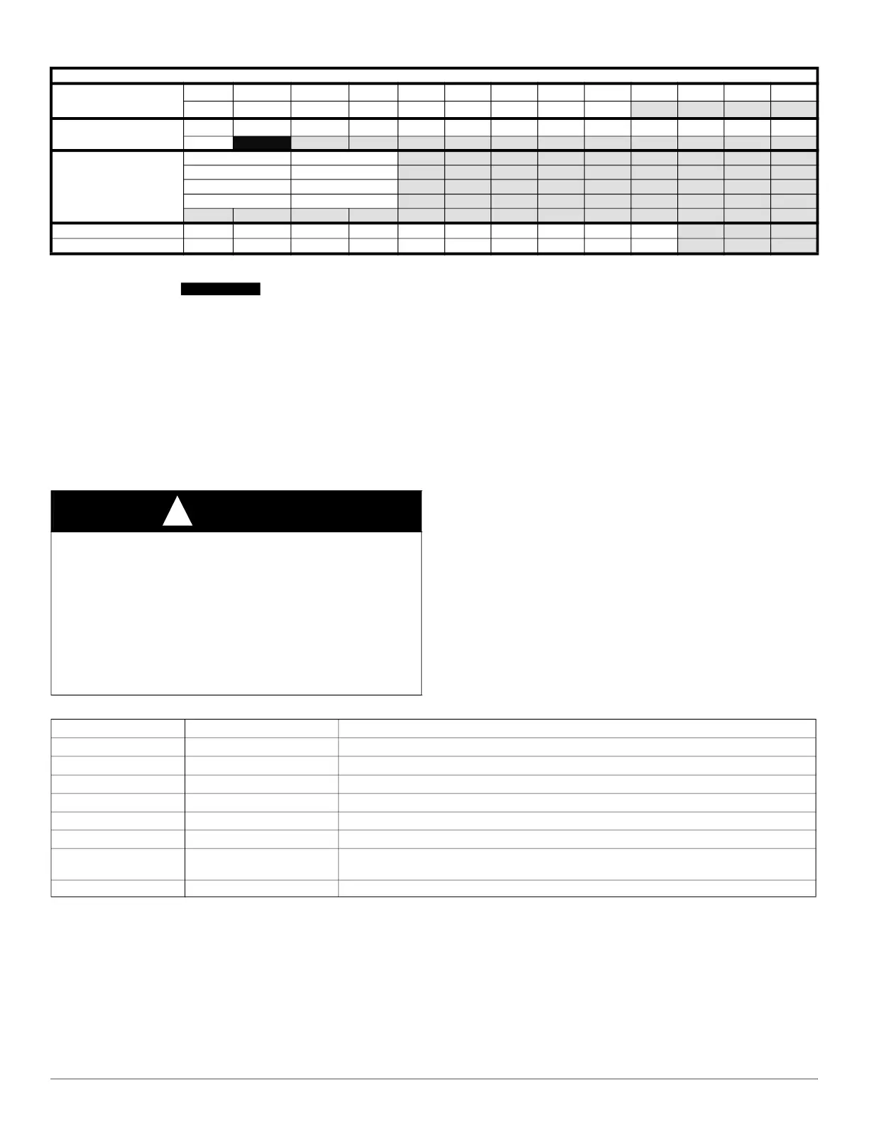
120C24--22
Available Cooling
Airflow Settings (CFM
650 700 740 800 875 925 975 1000 1050 1138 1200 1225
*
1300
1400 1480 1600 1625
†
1750
1850 1911 2000 2110
Available Constant Fan
Airflow Settings (CFM)
‡
650
700 740 800 875 925 975 1000 1050 1138 1200 1225 1300
1400
1480
Airflow reduces by 2% -
3% per 0.1 of ESP
above the noted static
for these airflow
settings
Airflow Setting ESP (in. w.c.)
1911 0.8
2000 0.7
2110 0.5
Max Cooling ESP
0.1 0.2 0.3 0.4 0.5 0.6 0.7 0.8 0.9 1
**
Max Cooling CFM
2175 2175 2175 2195 2170 2130 2080 2030 1975 1920
*. Low Cooling Default
†. High Cooling Default
‡. Constant Fan Default Not Recommended
**. Max Cooling values are test CFM all other airflows are standard CFM
Table 16 – Air Delivery - CFM (with filter) (Continued)
CAUTION
!
ELECTRICAL SHOCK HAZARD
Failure to follow this warning could result in personal injury, or death.
Blower access door switch removes 115-V power to control. No
component operation can occur unless switch is closed. Caution must
be taken when manually closing this switch for service purposes.
Do not tape or permanently allow the door switch to be bypassed.
Temporarily depress the door switch with one hand while accessing the
service buttons with your other hand. Do not touch uninsulated
electrical components.
Table 17 – System Status Display Codes
Display Operating Mode Notes:
iDl
Idle/Standby Mode No active demands
Ht-%rate
Heating Mode Gas Heating active - % rate
CL2
High Cooling Mode Cooling or Heat Pump active
CL1
Low Cooling Mode Cooling or Heat Pump active
Hpd
Heat Pump Defrost Mode Gas Heating cycle active during Heat Pump Defrost cycle
Cfn, CF2, CF3
Continuous Fan Mode Continuous Fan active
Blr
Blower Operating Mode
System connected to a communicating thermostat and running in cooling, heating, continuous
fan or DHUM mode
##.# Active Status Code See Fig. 59 or Furnace Service Label for codes
 Loading...