59MN7C: Installation, Start-up, Operating and Service and Maintenance Instructions
Manufacturer reserves the right to change, at any time, specifications and designs without notice and without obligations.
26
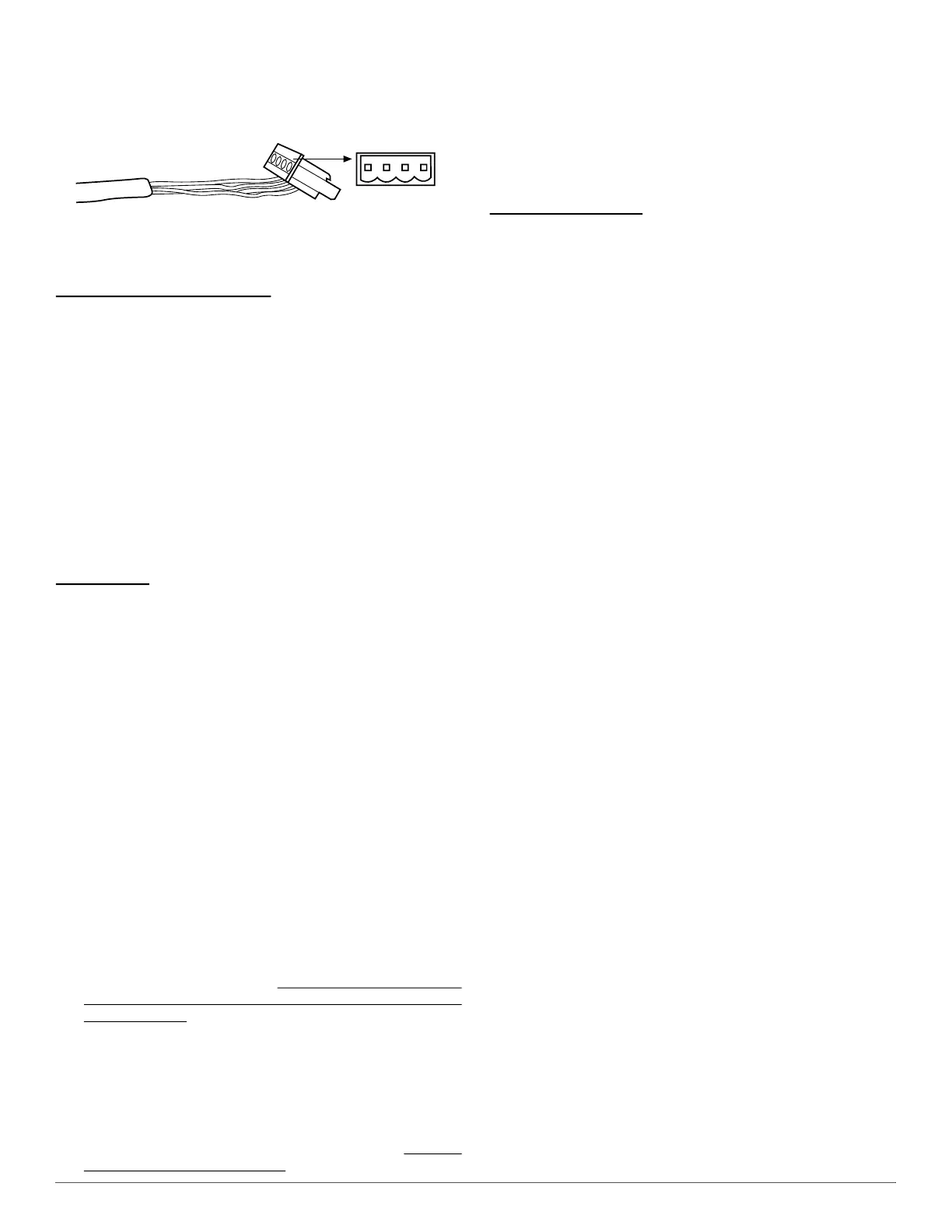
Communication Connector is used when the furnace is controlled by an
optimum communicating User Interface, see Fig. 36.
The communication plug is supplied with the User Interface. Refer to the
instructions supplied with the User Interface.
A03193
Fig. 36 – Communication Connector
NOTE: Wall controls may vary designations. Example: A = DX+, B =
DX-, C = C, D = R
Outside Air Thermistor (OAT)
Used in conjunction with communicating User Interface. Not required
when a standard type thermostat is used. Refer to the instructions
supplied with the User Interface for details.
24-V WIRING
Make field 24-V connections at the 24-V terminal strip, see Fig. 38.
Connect terminal Y/Y2 as shown in Fig. 33 for proper cooling operation.
Use only AWG No. 18, color-coded, copper thermostat wire.
NOTE: Use AWG No. 18 color-coded copper thermostat wire for
lengths up to 100 ft. (31 M). For wire lengths over 100 ft., use AWG No.
16 wire.
The 24-V circuit contains an automotive-type, 3-amp. fuse located on
the control. Any direct shorts during installation, service, or maintenance
could cause this fuse to blow. If fuse replacement is required, use ONLY
a 3-amp. fuse of identical size, see Fig. 38.
Thermostats
For best results, use a communicating wall control to control this
modulating furnace. A single stage or two-stage heating and cooling
thermostat can be used with the furnace. The furnace control board CPU
will control the furnace and outdoor unit staging. A two stage heating
and cooling thermostat can also be used to control the staging. However,
full modulating capability will not be available when the furnace staging
is controlled by the thermostat. Furnace staging will be limited to
Minimum and Maximum inputs or Intermediate and Maximum inputs
depending on the thermostat type selected in (Htt). For two stage
thermostat control of a 2-stage outdoor unit, navigate to (Ctt) and select
(2St). Refer to typical thermostat wiring diagrams and the Sequence of
Operation section for additional details. Consult the thermostat
installation instructions for specific information about configuring the
thermostat, see Fig. 38.
TEMPERATURE SENSORS
The furnace comes with a Return Air Temperature (RAT) sensor
installed on the control board and a Supply Air Temperature (SAT) for
installation in the field.
Install Supply Air Temperature (SAT) Sensor
1. Locate SAT sensor in main supply trunk after furnace and cooling
coil. Placing the SAT sensor after the first bend in main supply
trunk will yield the best readings. If this is not possible, by placing
the sensor further down the main trunk will allow for more mixing
and better results.
2. Drill a 1/4-in. hole at location in supply trunk where sensor will be
installed.
3. Insert sensor in hole and use as a template to mark the two (2)
mounting holes.
4. Drill two (2) 1/16-in. holes to accept No. 8 screws through
pre-drilled holes in duct temperature sensor back plate.
5. Use two (2) provided No. 8 sheet metal screws to mount the supply
air temperature sensor to the system.
6. Route SAT wire leads into furnace blower compartment along with
the thermostat wires. Use provided grommet to protect the wires
through the furnace casing.
7. Connect sensor wire leads to furnace control at the screw terminal
marked SAT. If additional wire length is needed, thermostat wire
and wire nuts can be used to extend the wires.
NOTE: When communications with the thermostat is present, the green
COMM light on the furnace control will be on.
Temperature Display
The SAT and RAT temperatures can be displayed on the control board 3
digit display. On the 3 digit display, navigate to (t°) and select F or C
(Default is off).When enabled, the display will cycle through the current
operating mode, SAT, RAT, and temperature differential during heating,
cooling and heat pump operation.The temperatures will not be displayed
in other operating modes.
ACCESSORIES (See Fig. 38 and Fig. 37.)
1. Electronic Air Cleaner (EAC)
Connect an accessory Electronic Air Cleaner (if used) using 1/4-in.
female quick connect terminals to the two male 1/4-in.
quick-connect terminals on the control board marked EAC-1 and
EAC-2. The terminals are rated for 115 VAC, 1.0 amps maximum
and are energized during blower motor operation.
2. Humidifier (HUM 24-V)
The HUM terminal is a 24 VAC output, energized when the blower
is operating during a call for heat.
Connect an accessory 24 VAC, 0.5 amp. maximum humidifier (if
used) to the ¼-in. male quick-connect HUM terminal and
COM/24-V screw terminal on the control board thermostat strip.
NOTE: If the humidifier has its own 24 VAC power supply, an isolation
relay may be required. Connect the 24 VAC coil of the isolation relay to
the HUM and COM/24-V screw terminal on the control board
thermostat strip, see Fig. 37.
3. Communication Connector (PL7)
This connection is used when the furnace is controlled by an
optional communicating User Interface instead of a standard
thermostat. The communication plug is supplied with the User
Interface. Refer to the instructions supplied with the User Interface
for complete details, see Fig. 38.
4. Outside Air Thermistor (OAT)
The OAT connection is used in conjunction with communicating
User Interface. It is not required when the furnace is controlled by a
standard type thermostat. Refer to the instructions supplied with the
User Interface for complete details.
Alternate Power Supplies
This furnace is designed to operate on utility generated power which has
a smooth sinusoidal waveform. If the furnace is to be operated on a
generator or other alternate power supply, the alternate power supply
must produce a smooth sinusoidal waveform for compatibility with the
furnace electronics. The alternate power supply must generate the same
voltage, phase, and frequency (Hz) as shown in Table 9 or the furnace
rating plate.
Power from an alternate power supply that is non-sinusoidal may
damage the furnace electronics or cause erratic operation.
Contact the alternate power supply manufacturer for specifications and
details.


 To Next Page