59MN7C: Installation, Start-up, Operating and Service and Maintenance Instructions
Manufacturer reserves the right to change, at any time, specifications and designs without notice and without obligations.
47
The Main Menu provides access to operating parameters of the furnace
control including airflows as well as other diagnostics. See Fig. 38 for
the location of the pushbuttons. Scroll through Main Menu by pressing
MENU/SELECT button. Press NEXT/OPTION to display the current
setting of the parameter (value will flash). Additional presses will scroll
through setting options. Press MENU/SELECT button to save a new
setting and return to the Main Menu. The display will flash three times to
confirm a new setting selection has been saved. Fig. 58 shows the flow
of the menu and settings. Table 18 provides additional information on
parameter adjustment and applicability.
NFC and Supported App Method
This furnace control board is also equipped with NFC (Near Field
Communication) technology which allows the adjustment of operating
parameters, diagnostics, and service via a field-supplied mobile device
with NFC capability and supported mobile app. Remove 115-V power
from the furnace control board to use this method. See Fig. 38 for the
location of the NFC antenna. Additional instructions and help may be
available through the supported mobile app.
Scan the mobile app QR Code on page 1 of this manual for more
information and a link to download the mobile app.
Bluetooth® Module
This unit is equipped with a module, which includes Bluetooth wireless
technology that allows a user to connect via an application on a phone or
tablet. It is recommended that the Bluetooth Module be activated during
the installation process.
Follow these steps to download and activate Bluetooth Module:
1. Download the app
Scan the mobile app QR code on the front page of this document, or
search your app store for Carrier Service Technician to download. The
app is available on phone and tablet devices. If you already have the app
downloaded, please ensure you have updated to the latest version.
To Activate Bluetooth Module:
1. Login to the Carrier Service Technician app using your
HVACPartners username and password.
2. On the App Home screen, tap the “Connect to Outdoor Unit or
Furnace” button. Please ensure your equipment is powered on For
best results, it is recommended to keep your mobile device within
10 feet of the equipment throughout this whole process.
NOTE: In order to connect to equipment using Bluetooth, you must
have Bluetooth enable on your mobile device, and you must allow the
Service Tech app to access Bluetooth and location services in your
device permissions. For more information on how to enable these
features and permissions, please consult documentation from your
device manufacturer.
3. The app will scan for nearby Bluetooth enabled equipment. To
activate a new unit, the app will display “New Equipment”. Tap on
that item and then select the Pair button.
4. The app will display the equipment Serial and Model number.
Please confirm these are correct for the equipment you are trying to
activate and tap continue.
5. The app will now automatically progress through the activation
process. Once the steps are complete, the unit is activated
successfully and your device will be automatically paired to the
equipment.
NOTE: You will only have to perform this activation once and you will
now be able to pair to this equipment directly with the app in the future.
Control Board Replacement
If the control board must be replaced, the new board must be
programmed with the correct Model Program Number before the furnace
will operate. Do NOT program the control board with a Model Program
Number different than what is specified on the rating plate. The control
may be programmed by either of these approved methods:
1. Use the supported mobile app to flash the model program onto the
board using Near Field Communication (NFC). Scan the QR code
on page 1 of this manual for more information and a link to
download the mobile app.
2. Use the correct Super Plug (available from distributor / replacement
component) for the control board to copy the correct model
program onto the new board.
Further details and instructions for these programming methods are provided with the replacement control board.
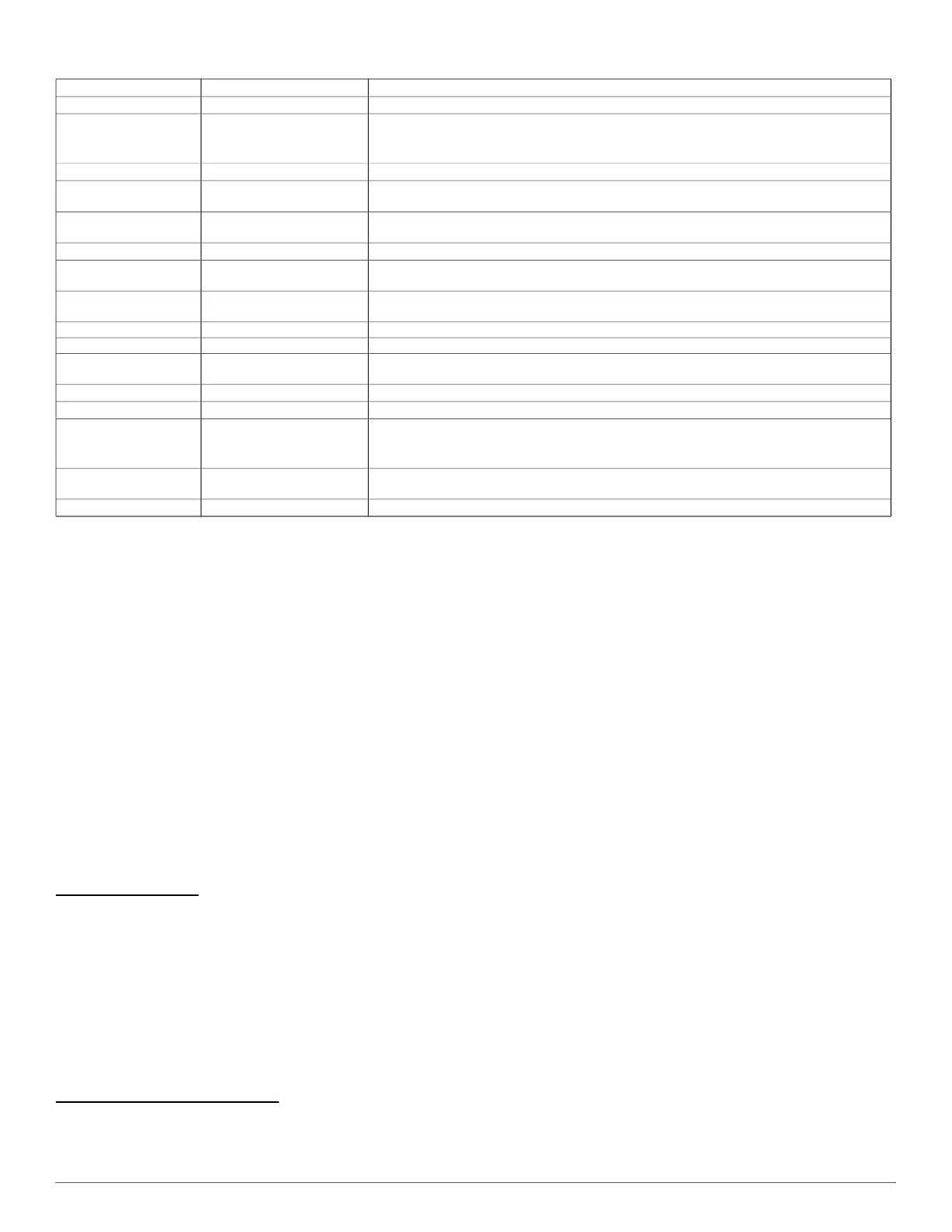
Table 18 – Main Menu Options
Display Menu Item Use
idL, Ht,...
Idle/Stand by Mode
Displays the current furnace operating mode or active fault code.
FLt
Last 7 faults that occurred
Faults code menu stores the 7 latest faults in memory. If no faults, None (
non) will be
displayed. To clear fault history, scroll to Clear (Clr) and press MENU/SELECT. See Fig. 59 or
Furnace Service Label for codes.
t°
Temperature Display On/Off
Enable supply and return air temperature display on control.
Ht
Heating blower speed
Heating Airflow Setting. Adjust higher to lower Temp. Rise; lower to increase Temp. Rise. See
Start-Up Procedures. See Fig. 58 for allowable selections and Table 16 for airflows.
CL2, CL1
Cooling and Heat Pump
blower speed
Cooling Airflow Setting. See Fig. 58 for allowable selections and Table 16 for airflows. Refer to
cooling or heat pump equipment data for required airflow settings.
Cfn
Constant Fan blower speed
Constant Fan Airflow Setting. See Fig. 58 for allowable selections and Table 16 for airflows.
HoD
Heat Blower-OFF Delay
Value shown in seconds. Shorter delays may leave unused heat in ducts. Longer delays may
blow cold air at the end of heating demands.
Cod Cool Blower-OFF Delay
Value shown in seconds. Shorter delays may leave unused energy in furnace coil. Longer
delays may re-evaporate condensate.
Htt Heating thermostat type Sets thermostat type.
Ctt Cooling thermostat type Sets thermostat type.
dir
Orientation upflow or
downflow
Adjusts display orientation 180 degrees between up flow (
UPF) and down flow (dnF).
bSt
Inducer Boost
Inducer speed boost
Air
Air
CFM display ON/Off
inF
Program # and Software
Do NOT program the control board with a Model Program Number different than what is
specified on the rating plate. Alternates displaying the saved Model Program Number (
pRG)
and Software Version (
uEr).
Ct
Component Test
Use to validate components are functioning as intended. See Component Self-Test
instructions in the Start-Up Procedures section.
rSt
Reset
Reset settings to Factory Default by selecting Yes (
YEs).


 To Next Page