59MN7C: Installation, Start-up, Operating and Service and Maintenance Instructions
Manufacturer reserves the right to change, at any time, specifications and designs without notice and without obligations.
63
9. Refer to furnace wiring diagram and reconnect wires to flame
rollout switch, gas valve, igniter, and flame sensor.
10. Turn on gas and electrical supplies to furnace.
11. Check furnace operation through 2 complete heat operating cycles.
Look at burners. Burner flames should be clear blue, almost
transparent, see Fig. 65.
12. Check for gas leaks.
13. Replace main furnace door.
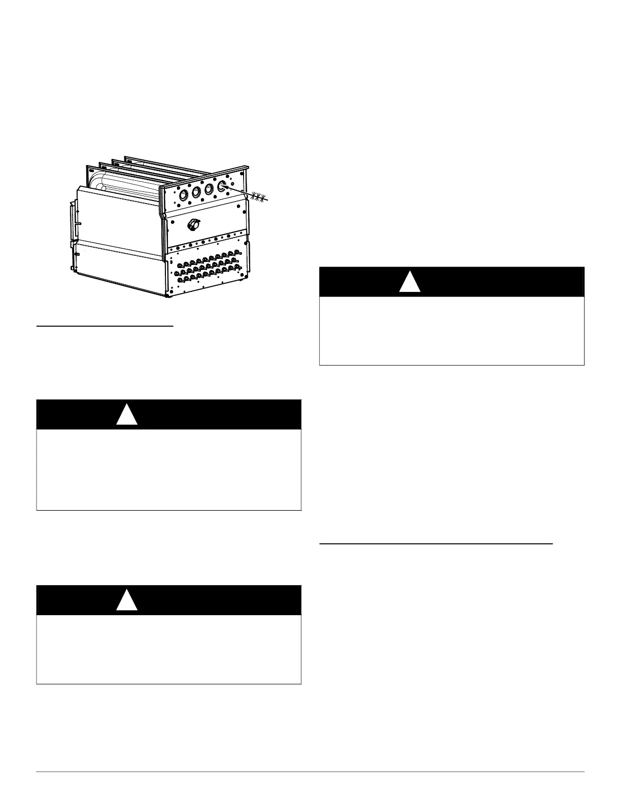
A11273
Fig. 70 – Cleaning Heat Exchanger Cell
Secondary Heat Exchangers
The condensing side (inside) of the secondary heat exchanger CANNOT
be serviced or inspected without complete removal of the heat exchanger
assembly. Detailed information on heat exchanger removal can be
obtained from your Distributor.
WINTERIZATION
Since the furnace uses a condensing heat exchanger, some water will
accumulate in the unit as a result of the heat transfer process. Therefore,
once it has been operated, it cannot be turned off and left off for an
extended period of time when temperatures will reach 32_F (0_C) or
lower unless winterized. Follow these procedures to winterize your
furnace:
1. Obtain propylene glycol (RV/swimming pool antifreeze or
equivalent).
2. Turn off gas and electrical supplies to your furnace.
3. Remove furnace control door.
4. Remove the top unused rubber plug from the port on the collector
box opposite the condensate trap, see Fig. 61.
5. Connect a field supplied 3/8-in. (9.5-mm) ID tube to the open port
on the collector box
6. Insert a field supplied funnel into the tube.
7. Pour 1 quart of anti-freeze solution into the funnel/tube. Antifreeze
should run through the inducer housing, overfill condensate trap
and flow to an open drain.
8. Replace the rubber plug in the port on the collector box.
9. Remove the middle unused rubber plug from the port on the
collector box opposite the condensate trap, see Fig. 61.
10. Repeat Steps 5 through 8.
11. If a condensate pump is used, check with pump manufacturer to
verify pump is safe for use with antifreeze used. Allow pump to
start and pump anti-freeze to open drain.
12. Replace main door.
13. When furnace is re-started, flush condensate pump with clear water
to check for proper operation before re-starting furnace.
14. Propylene glycol need not be removed before re-starting furnace.
SEQUENCE OF OPERATION
Using the schematic diagram, follow the sequence of operation through
the different modes, see Fig. 60. Read and follow the wiring diagram
very carefully!
NOTE: If a power interruption occurs during a call for heat (W/W1 or
W/W1-and-W2), the control will start a 90-second blower-only ON
period two seconds after power is restored, if the thermostat is still
calling for gas heating. The LED light will flash code 12 and display will
show (12.1) during the 90-sec period, after which the LED will be ON
continuous, as long as no faults are detected. After the 90-second period,
the furnace will respond to the thermostat normally.
The blower door must be installed for power to be conducted through the
blower door interlock switch ILK to the furnace control CPU,
transformer TRAN, inducer motor IDM, blower motor BLWM, hot
surface igniter HSI, and gas valve GV.
Communicating Control and Modulating Heating
Best comfort will be attained when a communicating wall control is used
with this product. Wiring and set-up instructions are provided with the
communicating control. See the furnace data sheet accessory section for
help in selecting the appropriate communicating control for this furnace.
When a communicating control is used, the furnace will modulate
through its full operation range, or can be limited via the minimum and
maximum CFM configurations.
Operation of the furnace at the beginning and end of each heating cycle
will be the same as detailed below in the Single-Stage Thermostat
section EXCEPT that the communicating control will send modulating
rate command signals through the communication bus rather than
energizing the 24-V thermostat terminals. Note that the R to W/W1
circuit signal will be controlled by the COMMR relay on the furnace
control. See the wiring diagram in Fig. 60.
Installer settings will be made via the wall control instead of the furnace
control push buttons when a wall control is connected.
CAUTION
!
UNIT AND PROPERTY DAMAGE HAZARD
Failure to follow this caution may result in unit component or property
damage.
If the furnace is installed in an unconditioned space where the ambient
temperatures may be 32_ F (0_ C) or lower, freeze protection measures
must be taken to prevent property or product damage.
CAUTION
!
UNIT COMPONENT DAMAGE HAZARD
Failure to follow this caution may result in damage to the furnace and
other property damage.
Do not use ethylene glycol (automotive antifreeze coolant or
equivalent). Failure of plastic components may occur.
CAUTION
!
UNIT OPERATION HAZARD
Failure to follow this caution may result in intermittent unit operation.
Furnace control must be grounded for proper operation or control will
lock out. Control is grounded through green/yellow wire routed to gas
valve and burner box screw.