viii
T-305
LIST OF ILLUSTRATIONS
FIGURE NUMBER Page
Figure A. Emergency Bypass for the Door Interlock System Safety--3....................................
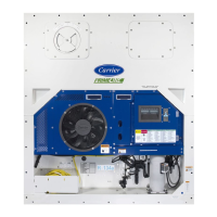
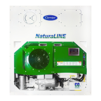
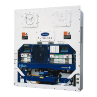
Figure 1. Refrigeration Unit -- Front Section 5......................................................
Figure 2. Evaporator Section 6...................................................................
Figure 3. Compressor Section 7..................................................................
Figure 4. Condenser Section 8...................................................................
Figure 5. Water-Cooled Condenser Section 9......................................................
Figure 6. Control Box Section 10..................................................................
Figure 7. Refrigeration Circuit Schematic 15........................................................
Figure 8. Temperature Control System 17..........................................................
Figure 9. Key Pad 18............................................................................
Figure 10. Display Module 18.....................................................................
Figure 11. Micro-Link 2i Controller 19..............................................................
Figure 12. Standard Configuration Report 26........................................................
Figure 13. Data Reader 28.......................................................................
Figure 14. Autotransformer 45....................................................................
Figure 15. Make Up Air Flow Chart 46.............................................................
Figure 16. Controller Operation -- Perishable Mode 49................................................
Figure 17. Controller Operation -- Frozen Mode 49...................................................
Figure 18. Perishable Mode 50....................................................................
Figure 19. Perishable Mode Heating 50............................................................
Figure 20. Frozen Mode 51.......................................................................
Figure 21. Defrost Mode 51.......................................................................
Figure 22. Service Valve 57......................................................................
Figure 23. Manifold Gage Set 57..................................................................
Figure 24. R-134a Manifold Gage/Hose Set 58......................................................
Figure 25. Refrigeration System Service Connections 58.............................................
Figure 26. Compressor Service Connections 60.....................................................
Figure 27. Compressor 61........................................................................
Figure 28. Exploded View of Valve Plate 62.........................................................
Figure 29. Bottom Plate Removed 62..............................................................
Figure 30. Oil Pump and Bearing Head 63..........................................................
Figure 31. Low Profile Oil Pump 63................................................................
Figure 32. Motor End Cover 63...................................................................
Figure 33. Equalizing Tube and Lock Screw Assembly 64............................................
Figure 34. Crankshaft Assembly 64................................................................
Figure 35. Suction Valve & Positioning Springs 64...................................................
Figure 36. Piston Ring 64........................................................................
Figure 37. High Pressure Switch Testing 66.........................................................
Figure 38. Water-Cooled Condenser Cleaning -- Forced Circulation 68.................................
F
igure 39.
Water Cooled Condenser Cleaning - Gravity Circulation 68..................................
Figure 40. Thermostatic Expansion Valve Bulb 69...................................................
Figure 41. Hermetic Thermostatic Expansion Valve 69...............................................
Figure 42. Hermetic Thermostatic Expansion Valve Brazing Procedure 69..............................
Figure 43. Evaporator Fan Locating Dimension 70...................................................

 Loading...

