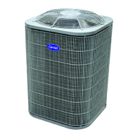
OUTDOOR UNIT INSTALLATION
17.3 The outdoor unit top discharge can be installed in any outside location on a ground level
or on a roof
17.3.1 GROUND INSTALLATION
x The outdoor unit may be installed at ground level on a solid base that will not shift or settle,
causing strain on the refrigerant lines and possible leaks. Maintain the clearances and install the
unit in a level position.
x Normal operating sound levels may be objectionable if the outdoor unit is placed directly under
windows of certain rooms (bedrooms, study, etc.).
x Top of unit discharge area must be unrestricted for at least 150 cm above the unit.
x If the unit is to be installed on a black-topped ground area, the unit should be raised sufficiently
above the roof or ground to avoid taking the accumulated layer of hot air into the outdoor unit.
Provide an adequate structural support.
17.3.2 ROOF INSTALLATION
x When installing the outdoor unit on a roof, the structure must be capable of supporting the total
weight of the unit, including a padded frame unit, rails, etc., which should be used to minimize the
transmission of sound or vibration into the conditioned space.
x If the unit is to be installed on a hot sun exposed roof, the unit should be raised sufficiently above
the roof or ground to avoid taking the accumulated layer of hot air into the outdoor unit. Provide
an adequate structural support.
17.3.3 UNIT PLACEMENT
1. Provide a base in the pre-determined location.
2. Remove the shipping carton and inspect for possible damage.
3. Compressor tie-down bolts should remain tightened.
4. Position the unit on the base provided.
17.3.4 IMPORTANT NOTE:
These instructions are intended as a method to tie-down system to cement slab as a securing
procedure. It is recommended to check Local codes for tie-down methods and protocols.
Step 1: Prior to installing clear pad of debris.
Step 2: Ensure cement pad is level
IMPORTANT
Then cement pad must be of the proper thickness to accommodate fasteners.
Step 3: Center the outdoor unit onto pad.
Step 4: Fasten 4 ( four ) L-shaped support angles onto outdoor unit base using 4 ( four ) Hex
washer head self tapping screws size 6 x 12 mm where indicated in detail below Fig.
IMPORTANT
Do not use screws longer than indicated and make sure that the L- shaped support angle is
attached on center of base where indicated in the figure. Damage will occur.
 Loading...